
Data Analysis: Main Menus and Toolbar
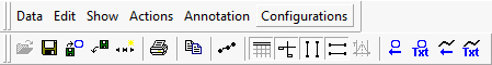
The Data Analysis main menus and associated toolbar are shown in Figure 1. Each menu is covered individually in a section below, with a table describing each menu's options. When present, the icon on the main toolbar representing the command is also displayed. You can click on one of the menu names just below to jump straight to its section.
Data --- Edit --- Show --- Actions --- Annotation --- Configurations
Data Menu
The Data Menu is used to open, close and save data files, and to set print options and print plots. It is described in Table 1.
Table 1: Data Menu Commands
Open
![]()
Opens a data file for analysis. Can only be selected if a file is not already open.
Close
Closes the currently opened data file.
Save
![]()
Saves formatting and screen configuration information, as well as all data, to a data file in Matlab File format (.mat). This will not overwrite the existing data file unless a Matlab file was already opened.
Save As
Same as the Save command, but allows you to select a new file name before saving.
Add a File to Current Plot
![]()
This command is deprecated (opening multiple files in Data Analysis is no longer supported).
Remove Active File from Plot
![]()
Removes the current file from the plot. Since only one file can be open at present, this command is now equivalent to selecting Close.
Save Data to a Subset File
![]()
Opens a dialog box to allow you to save a data file in a different format, or to save part of a large data file to a different file.
![]()
Opens a dialog box to allow you to print the current plot. You can select the printer, print range, and number of copies to print.
Print Preview
Shows a print preview of the current plot in the plotter area.
Print Setup
Opens a dialog to let you select the network, printer, paper size, and paper orientation for printing.
Recent Files
At the end of the Data menu is a list of the most recently opened data files, to make it easier for you to find them again if needed.
Edit Menu
The Edit Menu currently contains just the Copy command, described in Table 2.
Table 2: Edit Menu Commands
Copy
Copies the current plot to the Windows clipboard so it can be pasted into other programs.
Find in Files
This command is currently not implemented.
Show Menu
The Show Menu is used to enable or disable toolbars and other areas of the Data Analysis view, as well as to control cursors in the plotter area. Its commands can be found in Table 3.
Table 3: Show Menu Commands
Main Toolbar / Zoom Toolbar / Status Bar / Tool Dialog / Channel Value Pane / X-Axis Input Dialog / Plotter Setup Toolbar
Set or clear the checkbox next to any of these items to display or hide the associated area of Data Analysis.
Output Bar
![]()
Toggles the Output Bar on or off.
Zoom In
This command is currently not implemented.
Undo Zoom
This command is currently not implemented.
Refresh Screen
This command is currently not implemented.
View Cursor Position Values
![]()
Toggles the display of mouse cursor position values in the plotter area on or off.
View Time Cursors
![]()
Toggles both vertical line cursors in the plotter area on or off.
View Data Points
![]()
Toggles the highlighting of individual data points on or off for all plotted channels.
Actions Menu
The Actions Menu allows you to access controls for the X axis and to remove channels from the current plot; see Table 4.
Remove selected channels from plot
After selecting a number of channels, choose this option to remove them from the current plot.
Annotation Menu
This menu allows you to document or label your plots by adding arrows or text to them, which can be set to either remain stationary or move with channels to which they are linked. Table 5 contains this menu's commands.
Table 5: Annotation Menu Commands
Add Data Relative Text
![]()
Adds text to the plot positioned relative to a data channel, which moves as the channel does.
Add Data Relative Arrow
![]()
Adds an arrow to the plot positioned relative to a data channel, which moves as the channel does.
Add Screen Relative Text
![]()
Adds text to the plot that is positioned relative to the view area, independent of channel plots.
Add Screen Relative Arrow
![]()
Adds an arrow on the plot positioned relative to the view area, independent of channel plots.
To work with an annotation, first click on it to select it, then perform one of these actions::
Move: Hover the mouse pointer over the text or arrow until it changes to a four-arrow cursor. Then click and drag the annotation to new location.
Delete: Press the Delete key on the keyboard.
Edit Properties: Double-click the annotation after it is selected to open a properties dialog box.
Configurations Menu
Use this menu to save or load Data Analysis configurations, and set options for an object, a graph or the plotter as a whole. The menu commands are shown in Table 6.
Table 6: Configuration Menu Commands
Start new configuration
Resets the configuration to default values to start a new configuration.
Save current configuration
Saves the current configuration to a .cfg file.
Load configuration
Load a previously saved configuration .cfg file.
Program Default Options
Opens the Plotter Options dialog showing all options. Options set here become program defaults.
About
Displays the current version of the Data Analysis feature.