Messages View Column Headers
Overview
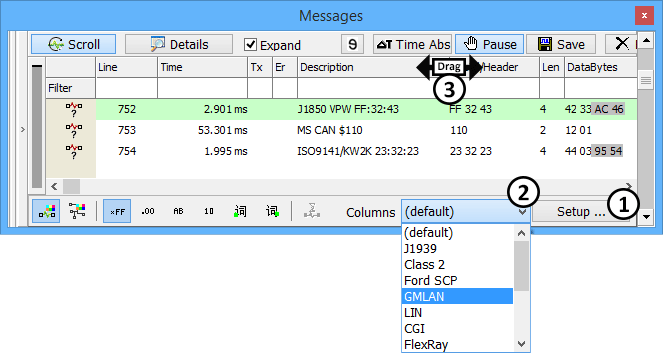
The columns visible in Messages view can be defined by the user. Vehicle Spy displays the default column set on initial start up. Select other column sets from the dropdown at the bottom of Messages view (Figure 1:![]() ). Create custom column sets by clicking the Setup button (Figure 1:
). Create custom column sets by clicking the Setup button (Figure 1:![]() ). Custom column sets are saved with your Vehicle Spy setup file. No need to recreate them each time Vehicle Spy is used.
). Custom column sets are saved with your Vehicle Spy setup file. No need to recreate them each time Vehicle Spy is used.
Column Actions
Figure 1 shows columns as seen in the Messages view. Click and drag on column dividers to resize them (Figure 1:![]() ).
).
Custom Column Sets
Custom column sets are a great tool for increasing efficiency. For example, you can create different column sets that you can quickly scroll through to see different types of information about a message. Use the Columns dropdown list (Figure 1:![]() ) to select predefined column sets. Press the Setup button (Figure 1:
) to select predefined column sets. Press the Setup button (Figure 1:![]() ) to build your own column set to add to the dropdown list.
) to build your own column set to add to the dropdown list.
Setting Up The Columns
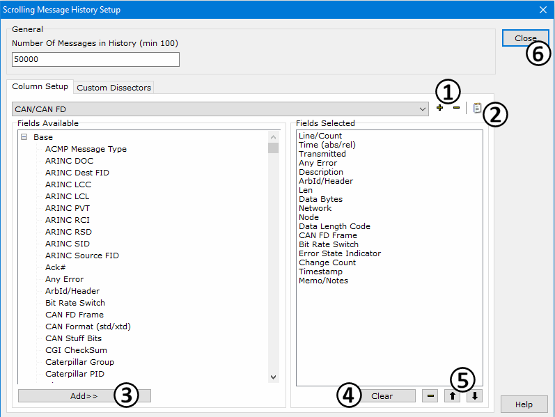
If you press the Setup button (Figure 1:![]() ), the setup dialog in Figure 2 will open. For more information on the General settings, please click here.
), the setup dialog in Figure 2 will open. For more information on the General settings, please click here.
Click the + button (Figure 2:![]() ) to create a new Column Setup. Click the edit button (Figure 2:
) to create a new Column Setup. Click the edit button (Figure 2:![]() ) to change the name of the new Column Setup. All possible column selections to choose from are listed in the Fields Available area on the left and are described in Table 1 below. To add columns to a setup, select an item in the list and click the Add>> button (Figure 2:
) to change the name of the new Column Setup. All possible column selections to choose from are listed in the Fields Available area on the left and are described in Table 1 below. To add columns to a setup, select an item in the list and click the Add>> button (Figure 2:![]() ) or just double click on the item.
) or just double click on the item.
All columns currently in your setup are displayed in the Fields Selected area on the right. Use the Clear and - buttons (Figure 2:![]() ) to clear the entire list or remove selected items one at a time. Individual items in this area can also be removed by just double clicking on them. Use the up/down arrow buttons (Figure 2:
) to clear the entire list or remove selected items one at a time. Individual items in this area can also be removed by just double clicking on them. Use the up/down arrow buttons (Figure 2:![]() ) to shift items up and down within the Fields Selected list.
) to shift items up and down within the Fields Selected list.
When you are finished building a Column Setup, click Close (Figure 2:![]() ) to return to Messages view. Make sure to save the vs3 or vs3zip file to save the new Column Setup.
) to return to Messages view. Make sure to save the vs3 or vs3zip file to save the new Column Setup.