VSpy 3 Documentation
All DocsProductsLearning CenterSupport
3.9.14
3.9.14
  • 🚗Welcome to the Vehicle Spy Help Documentation
  • Vehicle Spy Introduction
    • Vehicle Spy Overview
      • Vehicle Spy Tour
        • Vehicle Spy Tour 1: Bus Monitor
        • Vehicle Spy Tour 2: Signal Monitoring and Recording
        • Vehicle Spy Tour 3: Flight Recording
        • Vehicle Spy Tour 4: Node/Vehicle Simulation
        • Vehicle Spy Tour 5: Test Automation
        • Vehicle Spy Tour: Summary
    • Other Vehicle Spy Users
    • Vehicle Spy Specifications
    • Vehicle Spy Required Hardware PC System Requirements
    • Vehicle Spy Website
  • Vehicle Spy Tutorials
    • Vehicle Spy Tutorial Files
    • Getting Comfortable with the User Interface
    • Tabs in the User Interface
    • Tutorial 1: Basics of Vehicle Spy
      • Part 1 - Logon Screen
      • Part 2 - Monitor Message Traffic
      • Part 3 - Examine Messages
      • Part 4 - Your Message Specification in Action
      • Part 5 - Filtering Messages
      • Part 6 - More Ways to Filter in Vehicle Spy
      • Part 7 - Message Timestamps and Pausing
      • Part 8 - Save Your Messages View Buffer
      • Part 9 - Clear the Messages View Buffer
      • Part 10 - Exercises
    • Tutorial: Transmit Messages with Vehicle Spy
      • Part 1 - Load the Setup File
      • Part 2 - Enter a Transmit Message
      • Part 3 - Utilize the Alternate Workspace Panels
      • Part 4 - Manually Transmit a Message
      • Part 5 - Periodically Transmit a Message
      • Part 6 - Automatically Respond to a Message
      • Part 7 - Exercises
    • Tutorial: Decode Signals from Messages
      • Part 1 - Load a Setup File
      • Part 2 - Enter a Message
      • Part 3 - Enter an Equation for an Analog Value
      • Part 4 - View Message Data
      • Part 5 - View Message Data with the Signal List and Signal Plot
      • Part 6 - An Introduction to Signal Plot Features
      • Part 7 - Exercises
    • Tutorial: Database Setup
      • Part 1 - Platform Overview
      • Part 2 - Create a Platform
      • Part 3 - Adding Database Files
      • Part 4 - ECU Setup Wizard
      • Part 5 - Diagnostic Decoding
      • Part 6 - Conclusion
    • Tutorial: Basics of Capture Function Block and Graphical Panels
      • Part 1 - Setup the Simulation
      • Part 2 - Setup the Capture Function Blocks
      • Part 3 - Setup the Graphical Panel
      • Part 4 - Conclusion
    • Tutorial: Basics of Scripting and Playback
      • Part 1 - Setup Application Signals
      • Part 2 - Setup the Graphical Panel
      • Part 3 - Setup The Playback Function Block
      • Part 4 - Setup the Script Function Block
      • Part 5 - Summary
    • Tutorial: Request and Save DTC Data
      • Part 1 - Create a Diagnostic Job
      • Part 2 - Create Function Block to Request and Save Data
      • Part 3 - Make a Graphical Panel
      • Part 4 - Request, Save, and View the DTCs
      • Part 5 - Conclusion
    • Tutorial: DPS Programming Automation
      • Part 1 - Create DPS Programming Job
      • Part 2 - Create Function Block to Launch Programming Services
      • Part 3 - Make a Graphical Panel
      • Part 4 - Use the DPS Programming Graphical Panel
      • Part 5 - DPS Programming Automation Conclusion
    • Tutorial: Getting Fancy with Diagnostics
      • Part 1 - Read Data By Identifier Setup
      • Part 2 - Write Data by Identifier Setup
      • Part 3 - Writing the Read DID
      • Part 4 - Request Identifiers using Dynamically Define Data Identifier
      • Part 5 - Request the Dynamic Identifier
      • Part 6 - Conclusion
    • Tutorial: Sort Messages by ECU
      • Part 1 - Start a New Vehicle Spy Application
      • Part 2 - Enter ECU Source IDs to Sort
      • Part 3 - Setup Capture Type Function Blocks
      • Part 4 - Sort the ECU Messages
      • Part 5 - Setup Application Signals
      • Part 6 - Setup Playback Type Function Blocks
      • Part 7 - Setup Script Type Function Blocks
      • Part 8 - Construct a User Dialog
      • Part 9 - Run the Setup
    • Tutorial: Configuring and Using CoreMini
      • Part 1 - Creating a Tx Message
      • Part 2 - Logging Data
      • Part 3 - Loading the Script to the Hardware
      • Part 4 - How to Run the Script
      • Part 5 - Extracting Data
      • Part 6 - Viewing the Data
      • Part 7 - Conclusion
    • Tutorial: Simple Standalone Logging
      • Part 1 - Getting Started
      • Part 2 - Database/Hardware Setup
      • Part 3 - Channels
      • Part 4 - Checking Channel Selection
      • Part 5 - Standalone Logging
      • Part 6 - CoreMini Console
      • Part 7 - Extract Data
      • Part 8 - Conclusion
    • Tutorial: Standalone Video Logging
      • Tutorial: Standalone Video Logging - Part 1 - Setting up the Axis Camera
      • Tutorial: Standalone Video Logging - Part 2 - Setting Up Vehiclescape DAQ
      • Tutorial: Standalone Video Logging - Part 3 - Extracting the Video
    • Tutorial: C Code Interface
      • Part 1 - Create a Project
      • Part 2 - Adding Events
      • Part 3 - Running the Example
      • Part 4 - Debugging
      • Part 5 - Conclusion
    • Tutorial: How to run multiple devices in one VS3 file
      • Part 1 - Enabling Multiple Devices
      • Part 2 - Adding Devices
      • Part 3 - Assigning Devices
      • Part 4 - Syncing Time Across Multiple Devices
  • Tutorial Summary
  • Basic Operation of Vehicle Spy
    • The Logon Screen
    • Menus & Buttons
    • Running and Stopping
    • Data Directory
    • Create, Open, & Save Vehicle Spy Setups
    • Alternate Workspaces
    • Using Window Docking
  • Vehicle Spy Main Menus
    • Main Menu: File
      • The Logon Screen
      • Create, Open, & Save Vehicle Spy Setups
      • Import Function Blocks and Graphical Panels
      • Data Directory
      • Review Buffer
    • Main Menu: Setup
      • Setup a Network
      • Setup Platforms
      • Network Databases
      • ECUs View
        • Edit ECU Diagnostic Database
        • ECU Diagnostic Services Tab
      • Data Cache Disk Streaming
    • Main Menu: Spy Networks
      • Snapshot
      • Messages View
        • Messages View Filter Bar
          • Messages View Custom Filters
        • Messages View Top Toolbar
          • Message Details Pane
          • Reverse Engineering
          • Messages View Timestamping
          • Pause Messages View
          • Save the Buffer
          • Clear the Buffer
        • Messages View Column Headers
        • Messages View Column Filters
        • Messages View Buffer Display
          • Displaying Signals in Messages View
          • Buffer Progress Display
          • Messages View Task Menus
        • Messages View Bottom Toolbar
          • Color Filters
          • Messages View Data Byte Format
          • Messages View Setup
      • Message Editor
        • Messages Editor: Overview
        • Messages Editor: Receive, Transmit, & Database Tables
        • Add and Delete Messages
        • Messages Editor: Cut, Copy, and Paste
        • Messages Editor: Sort and Arrange
        • Messages Editor: Pick a Network
        • Messages Editor: Right Click Menu
        • Message PT, Trgt, and Src
        • Messages Editor: Message Fields
          • Message Key
          • Message Description
          • Message Type
          • Message Arbitration ID
          • Multiframe Message
            • Receive ISO15765-2 Multiframe Message
            • Transmit ISO15765-2 Multiframe Message
          • Message Length
          • Message Data Bytes
            • Transmit Long Messages
          • Message Source Node
          • Receive Message "Tx Msg" Field
          • Message Color
        • Message Signals
          • Live Edit
          • Message Signal Type
          • Message Signal Type Analog
          • Message Signal Type Digital
          • Message Signal Type State Encoded
          • Message Signal Type Text
          • Message Signal Type DTC
          • Understanding Bit and Byte : Bit Positions
          • Message Signal Format and Units
      • Transmit Panel
        • Ways to Transmit Messages
          • Auto Tx and Transmit Rate
        • Add and Delete Transmit Messages
        • Transmit Panel Filter Bar
        • Dynamic Transmit Message Bytes
      • Networks
        • Setup a Network
        • Network Statistics
        • Moving Messages Between Networks
      • TCP/IP
      • FlexRay Controllers
        • FlexRay Controllers: State/Action Tab
        • FlexRay Controllers: Configuration Tab
        • FlexRay Controllers: Registers Tab
      • FlexRay Cycles
      • Diagnostics
        • Diagnostics View
        • Diagnostics Setup
      • Diagnostics over IP (DoIP)
      • Simulator
      • ECUs View
        • GMLAN ECUs
        • ISO 14229 ECUs
        • Keyword 2000 ECUs
    • Main Menu: Measurement
      • VehicleScape DAQ
        • VehicleScape DAQ: Database/Hardware Setup Tab
        • VehicleScape DAQ: Channels Tab
        • VehicleScape DAQ: PC Logging Tab
        • VehicleScape DAQ: Standalone Logging Tab
          • Standalone Logging: Collections and Methods
            • Collections and Methods: Message Capture Method
              • Message Capture Method: Message Collection Options
              • Message Capture Method: Start Options
            • Message Capture Method: Stop Options
              • Message Capture Method: Stop Options: Finish After Collecting Messages or When Expression is True
              • Message Capture Method: Stop Options: Pre/Post Collection
              • Message Capture Method: Stop Options: One Shot Report
            • Message Capture Method: Restart Options
            • Message Capture Method: Upload to Wireless neoVI
            • Collections and Methods: Bus Query Method
            • Collections and Methods: Histogram Method
            • Collections and Methods: Ethernet DAQ Method
          • Standalone Logging: Status Reporting
          • Standalone Logging: Power Management
          • Standalone Logging: Generation Options
        • VehicleScape DAQ: Gateway
        • VehicleScape DAQ: Online Tab
      • Signal Views
        • Signal Plot
        • Signal List
      • Graphical Panels
        • Graphical Panels: Tools
          • Graphical Panel Controls: Common Control Properties
          • Graphical Panel Controls: LED
          • Graphical Panel Controls: Text Display
          • Graphical Panel Controls: Meter
          • Graphical Panel Controls: Function Block Button
          • Graphical Panel Controls: Tx Button
          • Graphical Panel Controls: On/Off Button
          • Graphical Panel Controls: Action Button
          • Graphical Panel Controls: Diag Job Action Button
          • Graphical Panel Controls: Bargraph
          • Graphical Panel Controls: Knob
          • Graphical Panel Controls: Grid
          • Graphical Panel Controls: Numeric Entry
          • Graphical Panel Controls: Graph
          • Graphical Panel Controls: Text Entry
          • Graphical Panel Controls: Graphical Display
          • Graphical Panel Controls: Drop Down List
          • Graphical Panel Controls: Message History
          • Graphical Panel Controls: Flash Control
          • Graphical Panel Controls: Radio Button
          • Graphical Panel Controls: Bitmap Button
          • Graphical Panel Controls: Panel Button
          • Graphical Panel Controls: Hex Edit
        • Graphical Panels: Add or Delete a Tool
        • Graphical Panels: Tool Properties
        • Graphical Panels: Move a Tool
        • Graphical Panels: Resize a Tool
        • Graphical Panels: Format (Align or Resize) a Tool Group
        • Graphical Panels: Add or Delete Panels
        • Graphical Panels: Select and Work With Panels
        • Graphical Panels: Panel Properties
        • Graphical Panels: Lock Panels
        • Floating Panels
      • Logging
      • MEP (XCP/CCP) - Memory Edit Protocol
        • MEP Setup
          • MEP Setup - Properties
          • MEP Setup - Import / Export
          • MEP Setup - DAQ Tables
          • MEP Setup - Security
          • MEP Setup - Memory / Hex / S19
        • MEP Value Editor
        • MEP Curve Editor
        • MEP Map Editor
        • Data Acquisition with CCP/XCP
      • Data Analysis
        • Data Analysis: Main Menus and Toolbar
        • Data Analysis: Zoom Toolbar
        • Data Analysis: X-Axis Input Toolbar and Dialog
        • Data Analysis: Plotter Setup Toolbar
      • Data Analysis: Tool Dialog
        • Data Analysis: Calculated Channels
      • Data Analysis: Plotter Area
        • Data Analysis: Plotter Options
        • Data Analysis: Advanced Plotting Methods
      • Data Analysis: Channel Value Pane
      • Data Analysis: Output Bar
      • GPS Maps
      • Video
    • Main Menu: Embedded Tools
      • ECU Flashing Documentation
        • 1. Introduction
        • 2. CAL Files and DIDs (Parameters)
        • 3. ISO 14229 Security (example)
        • 4. Requirements
        • 5. ECU Flash Designer View
        • 6. ECU Flash Manager View
        • 7. Remote Vehicle ECU Flashing
        • 8. Additional Features: ECU Flashing - EXE
      • DPS Archive Viewer
      • CAN Terminal
      • Intrepid ECU Flasher: Definitions
      • J1939 Address Manager
      • J1939 DTC Monitor
      • BitSmash
    • Main Menu: GMLAN
      • Virtual Networks
      • GM CGI Bus
    • Main Menu: Scripting and Automation
      • Function Blocks
        • Function Blocks Toolbar
        • Function Block List
        • Function Block Start Tab
        • Function Blocks Types
          • Script Type Function Block
          • Script Type Function Block: Script Toolbar
          • Script Type Function Block: Commands
            • Script Type Function Block Command: Clear History
            • Script Type Function Block Command: Clear Stats
            • Script Type Function Block Command: Comment
            • Script Type Function Block Command: CoreMini Action
            • Script Type Function Block Command: DAQ Action
            • Script Type Function Block Command: Diag Job Action
            • Script Type Function Block Command: Function Block Action
            • Script Type Function Block Commands: If, Else, Else If, End If
            • Script Type Function Block Command: Jump If
            • Script Type Function Block Command: Jump To
            • Script Type Function Block Command: Load Message Data
            • Script Type Function Block Command: Log Data
            • Script Type Function Block Commands: Start Loop and End Loop
            • Script Type Function Block Command: Pause
            • Script Type Function Block Command: Read Data
            • Script Type Function Block Command: Set Value
            • Script Type Function Block Command: Set Value If
            • Script Type Function Block Command: Show Panel
            • Script Type Function Block Command: Sleep
            • Script Type Function Block Command: Stop
            • Script Type Function Block Command: Test DTC
            • Script Type Function Block Command: Text API
            • Script Type Function Block Command: Transmit
            • Script Type Function Block Command: Wait For
            • Script Type Function Block Command: Wait Until
          • Script Type Function Block: Resetting the Present Flag
          • Script Type Function Block: Debugging Tools
          • Capture Type Function Block
            • Capture Type Function Block: Filter Tab
            • Capture Type Function Block: Stop and Trigger Tab
            • Capture Type Function Block: Storage Tab
            • Capture Type Function Block: Data Tab
          • Playback Type Function Block
          • Function Blocks Hotkeys
      • C Code Interface
        • Working with the C Code Interface
        • C Code Interface: Functions and Events
          • Functions and Events: Message Objects
          • Functions and Events: Application Signals
          • Functions and Events: Timers
          • Functions and Events: Common Functions and Events
          • Functions and Events: Graphical Panels
          • Functions and Events: Diagnostic Jobs
          • Functions and Events: Function Blocks
          • Functions and Events: Text API
          • Functions and Events: Network Indexes and Statistics
        • C Code Interface: Object Names, Debugging, and Common Mistakes
        • C Code Interface: Advanced Topics
        • C Code Interface: CAPL Conversion
      • Application Signals
        • Application Signals: Save and Restore
      • Text API Terminal
    • Main Menu: Run
    • Main Menu: Tools
      • Utilities: CoreMini Console
        • Utilities: CoreMini Control
        • Utilities: CoreMini Partitions
        • Utilities: CoreMini Advanced Settings
      • Utilities: Extract / Export
        • Utilities: Extract from SD Card
        • Utilities: Export VSB to Other Formats
        • Utilities: Export VSB Convert VSB (with VSDB) to Other Formats V using Command Prompt in Windows
        • Utilities: Export VSB to CSV format using DataExtract.exe
      • Tools: Problem Log
      • Utilities: File Conversions
        • VSB Editor
      • Tools: Utilities
        • Utilities: VS3EXE Generator
        • Utilities: Hardware Acceleration
        • Tools: Performance
        • Tools: Language
      • PLASMA / ION Setup
      • Tools: Options
        • Options: Spy Networks Tab
          • Spy Networks Tab: J1850 VPW Mode
        • Options: Performance Settings
        • Options: Multimedia
          • Multimedia: Joystick Setup
        • Options: Text API Options
        • Options: License System
          • License Upgrade Eligibility
        • Options: GPS Setup
        • Options: Data Directories
        • Options: Regional Settings
    • Main Menu: Help
      • Contact Information - Intrepid Control Systems, Inc.
      • Vehicle Spy Website
  • Shared Features in Vehicle Spy
    • Shared Features: Calculated Signal Editor
      • Shared Features: Calculated Analog or Digital Signals
      • Shared Features: Calculated Text Signals
    • Shared Features: DTC Database
    • Shared Features: Expression Builder
    • Shared Features: Predefined Function Keys
    • Shared Features: Starting with a Selected View
    • Shared Features: Widgets
  • Vehicle Network Interface Hardware
    • Vehicle Network Interface Hardware: neoVI FIRE
      • General Purpose IO
    • Vehicle Network Interface Hardware: neoVI RED
    • Vehicle Network Interface Hardware: neoVI Blue
      • General Purpose IO
    • Vehicle Network Interface Hardware: ValueCAN
      • Vehicle Network Interface Hardware: ValueCAN 4-2
      • Vehicle Network Interface Hardware: ValueCAN 4-4
      • Vehicle Network Interface Hardware: ValueCAN 4-2EL
      • Vehicle Network Interface Hardware: ValueCAN 4 Industrial
    • Vehicle Network Interface Hardware: RAD-wBMS
    • Vehicle Network Interface Hardware: RAD-A2B
    • Vehicle Network Interface Hardware: RAD-Gigastar
    • Vehicle Network Interface Hardware: RAD-Galaxy
    • Vehicle Network Interface Hardware: ValueLOG
    • Getting Started with neoECU
      • neoECU Requirements
      • neoECU 10
        • neoECU 10: IO Map
        • neoECU 10: Loading Scripts Over CAN
        • neoECU 10: Power Up and Buttons
        • neoECU 10: Examples
      • neoECU 12
      • neoECU 20
        • neoECU 20: Configuration
        • neoECU 20: IO Map
        • neoECU 20: Loading Scripts Over USB
        • neoECU 20: Examples
      • neoECU 22
      • neoECU Firmware Updates
      • neoECU Sleep Mode
    • Vehicle Spy Text API
      • Vehicle Spy Text API: ECU Object
      • Vehicle Spy Text API: Labview Interface
    • Vehicle Spy VSB file Spec
  • Application Notes
    • Application Note: CoreMini Partition Logging
      • Logging - Part 1: General Setup
      • Logging - Part 2: Function Block Setup
      • Logging - Part 3: Sending the Script to the Hardware
      • Logging - Part 4: Conclusion
    • Application Note: VehicleScape Standalone Logging
      • Application Note: VehicleScape Standalone Logging - Part 1: Message Collection Options
      • Application Note: VehicleScape Standalone Logging - Part 2: Collection and Restart Options
      • Application Note: VehicleScape Standalone Logging - Part 3: Reporting Options, Power Management and
      • Application Note: VehicleScape Standalone Logging - Part 4: neoVI MOTE Setup
    • Application Note: XCP Driver Example
      • Application Note: XCP Driver Example - Part 1: Process Overview
      • Application Note: XCP Driver Example - Part 2: Example XCP Driver
      • Application Note: XCP Driver Example - Part 3: ECU Simulation and Porting XCP Driver
    • Application Note: neoVI Logging neoECU DAQ
      • Application Note: neoVI Logging neoECU DAQ - Part 1: neoECU Setup
      • Application Note: neoVI Logging neoECU DAQ - Part 2: VehicleScape DAQ
      • Application Note: neoVI Logging neoECU DAQ - Part 3: Review Data
    • Application Note: Using the neoVI MOTE
      • Application Note: Using the neoVI MOTE - Part 1: Messages
      • Application Note: Using the neoVI MOTE - Part 2: Display on Screen
      • Application Note: Using the neoVI MOTE - Part 3: Using the Speaker
      • Application Note: Using the neoVI MOTE - Part 4: Home Screen and Conclusion
    • Application Note: Gateway Builder Tutorial
      • Tutorial - Gateway Builder - Part 1 - Intro
      • Tutorial - Gateway Builder - Part 2 - Gateway Builder Overview
      • Tutorial - Gateway Builder - Part 3 - Add Messages to Gateway Builder
      • Tutorial - Gateway Builder - Part 4 - Gateway Input Actions
      • Tutorial - Gateway Builder - Part 5 - Output Messages, Signals, and Triggers
    • Application Note: Dynamically Manipulating Application Signal Arrays
      • Application Note: Dynamically Manipulating Application Signal Arrays
      • Application Note: Dynamically Manipulating Application Signal Arrays
      • Application Note: Dynamically Manipulating Application Signal Arrays
      • Application Note: Dynamically Manipulating Application Signal Arrays
    • PHY Dashboard
    • Sample Replay Files
  • Contact Us
    • Contact Information - Intrepid Control Systems, Inc.
Powered by GitBook
LogoLogo

Applications

  • Cybersecurity
  • Data Logging
  • Simulate ECU Functions
  • Diagnostics, Testing and Validation

Products

  • Vehicle Network Adapters
  • Data Loggers
  • Software
  • Automotive Ethernet Tools

Support

  • Support Resources
  • Contact Support
  • Class Schedule & Registration
  • Training Video Library

Company

  • About
  • News
  • Events
  • Contact Us

Copyright © 2024 | All Rights Reserved

On this page
  • Advanced Extractor Options
  • General tab:
  • Regional Settings tab:
  • Video Settings tab:
  • Time Zone tab:
  • Advanced tab:
  • Export tab:
Edit on GitHub
  1. Vehicle Spy Main Menus
  2. Main Menu: Tools
  3. Utilities: Extract / Export

Utilities: Extract from SD Card

PreviousUtilities: Extract / ExportNextUtilities: Export VSB to Other Formats

The first tab of the interface (Figure 1) extracts data from SD cards. Properly formatted SD cards are named "LOGGER" and have Vehicle Spy Archive (VSA) files on them that must be converted to Vehicle Spy Binary (VSB) files to be useful. The VSB files can then be used directly in Vehicle Spy or to other file formats. Follow these steps to pull data from an SD card and put VSB files on a PC:

  1. Connect the SD card to the PC.

  2. In Source, select the "LOGGER" SD card.

  3. In Output, select where to put extracted VSB files on the PC.

  4. If needed, adjust the start/end times or Advanced Settings.

  5. Click the Extract All Files button to make the VSB files.

  6. Watch the "Parsing results" area for status updates.

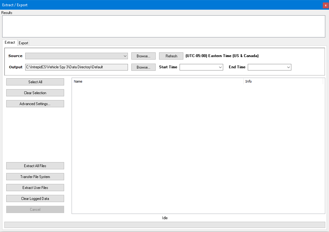
The Clear Log Data button will permanently clear all logged data from the SD card while leaving the CoreMini script intact. A yes/no dialog will confirm the choice because THIS CAN NOT BE UNDONE!

Advanced Extractor Options

The Advanced Settings button in Figure 1 above opens the dialog in Figure 2 below. The settings on the various tabs are briefly explained below. The Load Defaults button will revert all of the extractor settings back to their defaults.
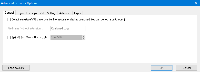
General tab:

Extracted files can be combined into one VSB file or split into limited size VSB files using the settings here.

Regional Settings tab:

This allows the control of how the date and time will appear. Changes to these settings also affect those found on the Tools-> Options->Regional Settings tab.

Video Settings tab:

This allows modification of how video is extracted and saved if cameras are being used to log video alongside other data in the particular setup.

Time Zone tab:

Logger data on the SD card is time stamped with UTC time (Universal Time Coordinated). The Time Zone selection here allows the choice to decide what the timestamps will be converted to in the extracted VSB files.

Advanced tab:

Options in the Advanced tab are used for trouble shooting. In most cases they will not be needed to be changed.

  • Enable Pre/Post cropping (enabled by default) - When this option is enabled, data from standalone captures that are configured as Pre/Post collections are trimmed to include only the data that meets the time or message count it was configured for. If this option is disabled, extra data before and after the trigger condition could be extracted.

  • Extract Older Records (disabled by default) - When data is extracted from the card, the timestamps are looked at to ensure the newest data is extracted. This option is available to help pull data with older time stamps.

  • Continue Scanning Even if First Record is Blank (disabled by default) - This option is another trouble shooting option. When this is enabled, the entire card is scanned to pull any data it find on the card. Using this option takes much longer to scan and in most cases it is not needed.

  • Ignore Timestamps (disabled by default) - If enabled, this option will pull all data regardless of the time stamp on the message and when the CoreMini script was loaded. When disabled, only messages newer than when the CoreMini was loaded are extracted.

  • Search All Records (disabled by default) - Turning this option on will search through the card for all possible records. When disabled, it will stop when a set number of blank entries are received. For normal operation, the blank entries serve as an end of collection.

  • Force Most CAN Gateway to CAN (disabled by default) - For use with older setups. If enabled it will force the MOST to CAN gateway to just CAN.

  • Zero neoVI GPS Coordinates When Invalid (disabled by default) - When enabled, Invalid GPS data from the hardware is set to 0.

Export tab:

Configurations for how data is exported and converted are made on the Export tab (Figure 3) of the Advanced Extractor Options.

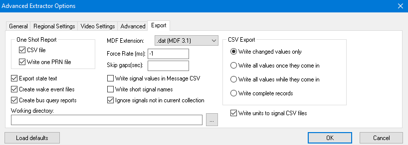
  • One Shot Report (Both checked by default) - This option gives the choice of using a *.CSV, *.PRN, or both for output of one shot collections.

  • Export State Text (Enabled by default) - The way state encoded signals are represented are controlled through this option. When checked, the state name is recorded rather than the state index. This option only affects CSV type exports.

  • Create Wake Events Files (Enabled by default) - When checked, Wake Event text files will be generated indicating when the hardware went to sleep during the collection time span.

  • Create Bus Query Reports (Enabled by default) - Enabled, Bus query reports are generated when bus query collections are configured.

  • MDF Extension (.dat is default) - The MDF file type has different data type outputs. The Extension gives the option to select the file extension for MDF outputs. Common file extensions are *.DAT, *.LOG, and *.MDF.

  • Write Signal Values in Message CSV (Disabled by default) - This option enables and disables adding signal information in message based CSV export files. Excluding this information will decrease the output file size, but require a database when attempting to look at the signals in the messages.

  • Write short signal names (Disabled by default) - When enabled, the signals are saved with their shorter names pulled from the database is applicable.

  • Ignore Signals not in Current Collection (Enabled by default) - This option gives the choice to only exporting signals that were originally defined for that collection.

  • Working directory - Allows the ability to change the directory where the extracted files will be saved to.

  • CSV Export ("Write Changed Values only" by default) - The signal based CSV can be saved in a few different formats. Different options will require different amounts of space to save.

    • Write Changed Values only - Only creates an entry for that signal when the data changes

    • Write All Values Once They Come In - Values only be added once the message is received.

    • Write All Values While They Come In - Values will only be during the duration that the message is active during the collection.

    • Write Complete Records - Uses the most space but has values entered in for every cell.

Extract / Export
standalone logger
exported
Figure 1: Use the Extract Tab to convert VSA files on an SD card to VSB files on a PC.
Figure 2: There are many settings to help customize data extraction from logger SD cards.
Figure 3: Advanced Export Options