
GPS Maps
Select a Map Application
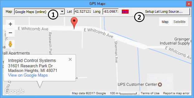
The Map dropdown (Figure 1:![]() ) selects which internet map application to use. Click and drag on the map to move it around and use the mouse wheel to zoom in and out. Each map application has custom built-in features and outside sources of help, so they are not explained further here.
) selects which internet map application to use. Click and drag on the map to move it around and use the mouse wheel to zoom in and out. Each map application has custom built-in features and outside sources of help, so they are not explained further here.
Set Up the GPS Data Source
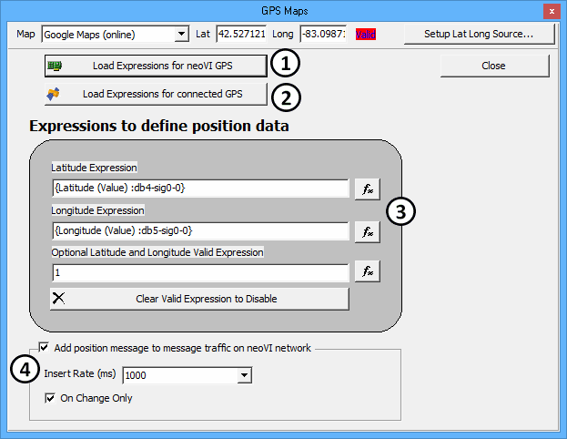
Click Setup Lat Long Source (Figure 1:![]() ) to open the setup dialog (Figure 2) and match the input expressions to one of these types of GPS data sources:
) to open the setup dialog (Figure 2) and match the input expressions to one of these types of GPS data sources:
GPS Data Source = neoVI GPS (ICS Logger)
Some ICS loggers have a GPS receiver that can log GPS data to a virtual "neoVI" network. The messages and their signals are predefined in Vehicle Spy's Messages Editor, Database view, neoVI network with ArbIDs $110 to $116. Click Load Expressions for neoVI GPS (Figure 2:![]() ) to set the input expressions for GPS Maps to match the neoVI network database signals.
) to set the input expressions for GPS Maps to match the neoVI network database signals.
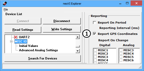
VSpy Setup Hardware, neoVI Explorer Connect, MISC IO, set Report GPS Coordinates = ON, Write Settings. (Figure 3:
 )
)
GPS Data Source = Connected GPS (GPS Receiver)
Vehicle Spy can acquire data directly from a GPS receiver connected to a PC serial communications port. The link is setup on the Tools -> Options -> GPS tab. The GPS data is available in the Expression Builder under Misc/GPS. Click Load Expressions for connected GPS (Figure 2:![]() ) to set the input expressions for GPS Maps to match the Expression Builder Misc/GPS signals.
) to set the input expressions for GPS Maps to match the Expression Builder Misc/GPS signals.
GPS Data Source = Custom Expressions (Vehicle ECU)
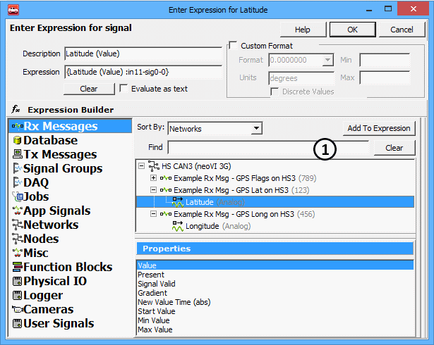
The GPS messages and their signals must first be defined in Vehicle Spy's Messages Editor Receive or Database views. Once defined, the GPS signals can then be assigned to the GPS Maps Latitude and Longitude expressions by clicking their fx button (Figure 2:![]() ) and using the Expression Builder. (Figure 4)
) and using the Expression Builder. (Figure 4)
Send GPS Maps Data to the neoVI Network (Optional)
If the GPS data source* is a GPS Receiver or Vehicle ECU then GPS Maps can gate the GPS data to the neoVI network by transmitting database GPS messages $110 to $112. To enable the feature, set the checkbox ON for Add position message to message traffic on neoVI network. (Figure 2:![]() ) Select an Insert Rate (ms) to set the periodic rate of the neoVI network messages. If On Change Only is enabled then the messages are sent only when the data differs from the previous transmission.
) Select an Insert Rate (ms) to set the periodic rate of the neoVI network messages. If On Change Only is enabled then the messages are sent only when the data differs from the previous transmission.