VSpy 3 Documentation
All DocsProductsLearning CenterSupport
3.9.13
3.9.13
  • 🚗Welcome to the Vehicle Spy Help Documentation
  • Vehicle Spy Introduction
    • Vehicle Spy Overview
      • Vehicle Spy Tour
        • Vehicle Spy Tour 1: Bus Monitor
        • Vehicle Spy Tour 2: Signal Monitoring and Recording
        • Vehicle Spy Tour 3: Flight Recording
        • Vehicle Spy Tour 4: Node/Vehicle Simulation
        • Vehicle Spy Tour 5: Test Automation
        • Vehicle Spy Tour: Summary
    • Other Vehicle Spy Users
    • Vehicle Spy Specifications
    • Vehicle Spy Required Hardware PC System Requirements
    • Vehicle Spy Website
  • Vehicle Spy Tutorials
    • Vehicle Spy Tutorial Files
    • Getting Comfortable with the User Interface
    • Tabs in the User Interface
    • Tutorial 1: Basics of Vehicle Spy
      • Part 1 - Logon Screen
      • Part 2 - Monitor Message Traffic
      • Part 3 - Examine Messages
      • Part 4 - Your Message Specification in Action
      • Part 5 - Filtering Messages
      • Part 6 - More Ways to Filter in Vehicle Spy
      • Part 7 - Message Timestamps and Pausing
      • Part 8 - Save Your Messages View Buffer
      • Part 9 - Clear the Messages View Buffer
      • Part 10 - Exercises
    • Tutorial: Transmit Messages with Vehicle Spy
      • Part 1 - Load the Setup File
      • Part 2 - Enter a Transmit Message
      • Part 3 - Utilize the Alternate Workspace Panels
      • Part 4 - Manually Transmit a Message
      • Part 5 - Periodically Transmit a Message
      • Part 6 - Automatically Respond to a Message
      • Part 7 - Exercises
    • Tutorial: Decode Signals from Messages
      • Part 1 - Load a Setup File
      • Part 2 - Enter a Message
      • Part 3 - Enter an Equation for an Analog Value
      • Part 4 - View Message Data
      • Part 5 - View Message Data with the Signal List and Signal Plot
      • Part 6 - An Introduction to Signal Plot Features
      • Part 7 - Exercises
    • Tutorial: Database Setup
      • Part 1 - Platform Overview
      • Part 2 - Create a Platform
      • Part 3 - Adding Database Files
      • Part 4 - ECU Setup Wizard
      • Part 5 - Diagnostic Decoding
      • Part 6 - Conclusion
    • Tutorial: Basics of Capture Function Block and Graphical Panels
      • Part 1 - Setup the Simulation
      • Part 2 - Setup the Capture Function Blocks
      • Part 3 - Setup the Graphical Panel
      • Part 4 - Conclusion
    • Tutorial: Basics of Scripting and Playback
      • Part 1 - Setup Application Signals
      • Part 2 - Setup the Graphical Panel
      • Part 3 - Setup The Playback Function Block
      • Part 4 - Setup the Script Function Block
      • Part 5 - Summary
    • Tutorial: Request and Save DTC Data
      • Part 1 - Create a Diagnostic Job
      • Part 2 - Create Function Block to Request and Save Data
      • Part 3 - Make a Graphical Panel
      • Part 4 - Request, Save, and View the DTCs
      • Part 5 - Conclusion
    • Tutorial: DPS Programming Automation
      • Part 1 - Create DPS Programming Job
      • Part 2 - Create Function Block to Launch Programming Services
      • Part 3 - Make a Graphical Panel
      • Part 4 - Use the DPS Programming Graphical Panel
      • Part 5 - DPS Programming Automation Conclusion
    • Tutorial: Getting Fancy with Diagnostics
      • Part 1 - Read Data By Identifier Setup
      • Part 2 - Write Data by Identifier Setup
      • Part 3 - Writing the Read DID
      • Part 4 - Request Identifiers using Dynamically Define Data Identifier
      • Part 5 - Request the Dynamic Identifier
      • Part 6 - Conclusion
    • Tutorial: Sort Messages by ECU
      • Part 1 - Start a New Vehicle Spy Application
      • Part 2 - Enter ECU Source IDs to Sort
      • Part 3 - Setup Capture Type Function Blocks
      • Part 4 - Sort the ECU Messages
      • Part 5 - Setup Application Signals
      • Part 6 - Setup Playback Type Function Blocks
      • Part 7 - Setup Script Type Function Blocks
      • Part 8 - Construct a User Dialog
      • Part 9 - Run the Setup
    • Tutorial: Configuring and Using CoreMini
      • Part 1 - Creating a Tx Message
      • Part 2 - Logging Data
      • Part 3 - Loading the Script to the Hardware
      • Part 4 - How to Run the Script
      • Part 5 - Extracting Data
      • Part 6 - Viewing the Data
      • Part 7 - Conclusion
    • Tutorial: Simple Standalone Logging
      • Part 1 - Getting Started
      • Part 2 - Database/Hardware Setup
      • Part 3 - Channels
      • Part 4 - Checking Channel Selection
      • Part 5 - Standalone Logging
      • Part 6 - CoreMini Console
      • Part 7 - Extract Data
      • Part 8 - Conclusion
    • Tutorial: Standalone Video Logging
      • Tutorial: Standalone Video Logging - Part 1 - Setting up the Axis Camera
      • Tutorial: Standalone Video Logging - Part 2 - Setting Up Vehiclescape DAQ
      • Tutorial: Standalone Video Logging - Part 3 - Extracting the Video
    • Tutorial: C Code Interface
      • Part 1 - Create a Project
      • Part 2 - Adding Events
      • Part 3 - Running the Example
      • Part 4 - Debugging
      • Part 5 - Conclusion
    • Tutorial: How to run multiple devices in one VS3 file
      • Part 1 - Enabling Multiple Devices
      • Part 2 - Adding Devices
      • Part 3 - Assigning Devices
      • Part 4 - Syncing Time Across Multiple Devices
  • Tutorial Summary
  • Basic Operation of Vehicle Spy
    • The Logon Screen
    • Menus & Buttons
    • Running and Stopping
    • Data Directory
    • Create, Open, & Save Vehicle Spy Setups
    • Alternate Workspaces
    • Using Window Docking
  • Vehicle Spy Main Menus
    • Main Menu: File
      • The Logon Screen
      • Create, Open, & Save Vehicle Spy Setups
      • Import Function Blocks and Graphical Panels
      • Data Directory
      • Review Buffer
    • Main Menu: Setup
      • Setup a Network
      • Setup Platforms
      • Network Databases
      • ECUs View
        • Edit ECU Diagnostic Database
        • ECU Diagnostic Services Tab
      • Data Cache Disk Streaming
    • Main Menu: Spy Networks
      • Snapshot
      • Messages View
        • Messages View Filter Bar
          • Messages View Custom Filters
        • Messages View Top Toolbar
          • Message Details Pane
          • Reverse Engineering
          • Messages View Timestamping
          • Pause Messages View
          • Save the Buffer
          • Clear the Buffer
        • Messages View Column Headers
        • Messages View Column Filters
        • Messages View Buffer Display
          • Displaying Signals in Messages View
          • Buffer Progress Display
          • Messages View Task Menus
        • Messages View Bottom Toolbar
          • Color Filters
          • Messages View Data Byte Format
          • Messages View Setup
      • Message Editor
        • Messages Editor: Overview
        • Messages Editor: Receive, Transmit, & Database Tables
        • Add and Delete Messages
        • Messages Editor: Cut, Copy, and Paste
        • Messages Editor: Sort and Arrange
        • Messages Editor: Pick a Network
        • Messages Editor: Right Click Menu
        • Message PT, Trgt, and Src
        • Messages Editor: Message Fields
          • Message Key
          • Message Description
          • Message Type
          • Message Arbitration ID
          • Multiframe Message
            • Receive ISO15765-2 Multiframe Message
            • Transmit ISO15765-2 Multiframe Message
          • Message Length
          • Message Data Bytes
            • Transmit Long Messages
          • Message Source Node
          • Receive Message "Tx Msg" Field
          • Message Color
        • Message Signals
          • Live Edit
          • Message Signal Type
          • Message Signal Type Analog
          • Message Signal Type Digital
          • Message Signal Type State Encoded
          • Message Signal Type Text
          • Message Signal Type DTC
          • Understanding Bit and Byte : Bit Positions
          • Message Signal Format and Units
      • Transmit Panel
        • Ways to Transmit Messages
          • Auto Tx and Transmit Rate
        • Add and Delete Transmit Messages
        • Transmit Panel Filter Bar
        • Dynamic Transmit Message Bytes
      • Networks
        • Setup a Network
        • Network Statistics
        • Moving Messages Between Networks
      • TCP/IP
      • FlexRay Controllers
        • FlexRay Controllers: State/Action Tab
        • FlexRay Controllers: Configuration Tab
        • FlexRay Controllers: Registers Tab
      • FlexRay Cycles
      • Diagnostics
        • Diagnostics View
        • Diagnostics Setup
      • Diagnostics over IP (DoIP)
      • Simulator
      • ECUs View
        • GMLAN ECUs
        • ISO 14229 ECUs
        • Keyword 2000 ECUs
    • Main Menu: Measurement
      • VehicleScape DAQ
        • VehicleScape DAQ: Database/Hardware Setup Tab
        • VehicleScape DAQ: Channels Tab
        • VehicleScape DAQ: PC Logging Tab
        • VehicleScape DAQ: Standalone Logging Tab
          • Standalone Logging: Collections and Methods
            • Collections and Methods: Message Capture Method
              • Message Capture Method: Message Collection Options
              • Message Capture Method: Start Options
            • Message Capture Method: Stop Options
              • Message Capture Method: Stop Options: Finish After Collecting Messages or When Expression is True
              • Message Capture Method: Stop Options: Pre/Post Collection
              • Message Capture Method: Stop Options: One Shot Report
            • Message Capture Method: Restart Options
            • Message Capture Method: Upload to Wireless neoVI
            • Collections and Methods: Bus Query Method
            • Collections and Methods: Histogram Method
            • Collections and Methods: Ethernet DAQ Method
          • Standalone Logging: Status Reporting
          • Standalone Logging: Power Management
          • Standalone Logging: Generation Options
        • VehicleScape DAQ: Gateway
        • VehicleScape DAQ: Online Tab
      • Signal Views
        • Signal Plot
        • Signal List
      • Graphical Panels
        • Graphical Panels: Tools
          • Graphical Panel Controls: Common Control Properties
          • Graphical Panel Controls: LED
          • Graphical Panel Controls: Text Display
          • Graphical Panel Controls: Meter
          • Graphical Panel Controls: Function Block Button
          • Graphical Panel Controls: Tx Button
          • Graphical Panel Controls: On/Off Button
          • Graphical Panel Controls: Action Button
          • Graphical Panel Controls: Diag Job Action Button
          • Graphical Panel Controls: Bargraph
          • Graphical Panel Controls: Knob
          • Graphical Panel Controls: Grid
          • Graphical Panel Controls: Numeric Entry
          • Graphical Panel Controls: Graph
          • Graphical Panel Controls: Text Entry
          • Graphical Panel Controls: Graphical Display
          • Graphical Panel Controls: Drop Down List
          • Graphical Panel Controls: Message History
          • Graphical Panel Controls: Flash Control
          • Graphical Panel Controls: Radio Button
          • Graphical Panel Controls: Bitmap Button
          • Graphical Panel Controls: Panel Button
          • Graphical Panel Controls: Hex Edit
        • Graphical Panels: Add or Delete a Tool
        • Graphical Panels: Tool Properties
        • Graphical Panels: Move a Tool
        • Graphical Panels: Resize a Tool
        • Graphical Panels: Format (Align or Resize) a Tool Group
        • Graphical Panels: Add or Delete Panels
        • Graphical Panels: Select and Work With Panels
        • Graphical Panels: Panel Properties
        • Graphical Panels: Lock Panels
        • Floating Panels
      • Logging
      • MEP (XCP/CCP) - Memory Edit Protocol
        • MEP Setup
          • MEP Setup - Properties
          • MEP Setup - Import / Export
          • MEP Setup - DAQ Tables
          • MEP Setup - Security
          • MEP Setup - Memory / Hex / S19
        • MEP Value Editor
        • MEP Curve Editor
        • MEP Map Editor
        • Data Acquisition with CCP/XCP
      • Data Analysis
        • Data Analysis: Main Menus and Toolbar
        • Data Analysis: Zoom Toolbar
        • Data Analysis: X-Axis Input Toolbar and Dialog
        • Data Analysis: Plotter Setup Toolbar
      • Data Analysis: Tool Dialog
        • Data Analysis: Calculated Channels
      • Data Analysis: Plotter Area
        • Data Analysis: Plotter Options
        • Data Analysis: Advanced Plotting Methods
      • Data Analysis: Channel Value Pane
      • Data Analysis: Output Bar
      • GPS Maps
      • Video
    • Main Menu: Embedded Tools
      • DPS Archive Viewer
      • CAN Terminal
      • Intrepid ECU Flasher: Definitions
      • J1939 Address Manager
      • J1939 DTC Monitor
      • BitSmash
    • Main Menu: GMLAN
      • Virtual Networks
      • GM CGI Bus
    • Main Menu: Scripting and Automation
      • Function Blocks
        • Function Blocks Toolbar
        • Function Block List
        • Function Block Start Tab
        • Function Blocks Types
          • Script Type Function Block
          • Script Type Function Block: Script Toolbar
          • Script Type Function Block: Commands
            • Script Type Function Block Command: Clear History
            • Script Type Function Block Command: Clear Stats
            • Script Type Function Block Command: Comment
            • Script Type Function Block Command: CoreMini Action
            • Script Type Function Block Command: DAQ Action
            • Script Type Function Block Command: Diag Job Action
            • Script Type Function Block Command: Function Block Action
            • Script Type Function Block Commands: If, Else, Else If, End If
            • Script Type Function Block Command: Jump If
            • Script Type Function Block Command: Jump To
            • Script Type Function Block Command: Load Message Data
            • Script Type Function Block Command: Log Data
            • Script Type Function Block Commands: Start Loop and End Loop
            • Script Type Function Block Command: Pause
            • Script Type Function Block Command: Read Data
            • Script Type Function Block Command: Set Value
            • Script Type Function Block Command: Set Value If
            • Script Type Function Block Command: Show Panel
            • Script Type Function Block Command: Sleep
            • Script Type Function Block Command: Stop
            • Script Type Function Block Command: Test DTC
            • Script Type Function Block Command: Text API
            • Script Type Function Block Command: Transmit
            • Script Type Function Block Command: Wait For
            • Script Type Function Block Command: Wait Until
          • Script Type Function Block: Resetting the Present Flag
          • Script Type Function Block: Debugging Tools
          • Capture Type Function Block
            • Capture Type Function Block: Filter Tab
            • Capture Type Function Block: Stop and Trigger Tab
            • Capture Type Function Block: Storage Tab
            • Capture Type Function Block: Data Tab
          • Playback Type Function Block
          • Function Blocks Hotkeys
      • C Code Interface
        • Working with the C Code Interface
        • C Code Interface: Functions and Events
          • Functions and Events: Message Objects
          • Functions and Events: Application Signals
          • Functions and Events: Timers
          • Functions and Events: Common Functions and Events
          • Functions and Events: Graphical Panels
          • Functions and Events: Diagnostic Jobs
          • Functions and Events: Function Blocks
          • Functions and Events: Text API
          • Functions and Events: Network Indexes and Statistics
        • C Code Interface: Object Names, Debugging, and Common Mistakes
        • C Code Interface: Advanced Topics
        • C Code Interface: CAPL Conversion
      • Application Signals
        • Application Signals: Save and Restore
      • Text API Terminal
    • Main Menu: Run
    • Main Menu: Tools
      • Utilities: CoreMini Console
        • Utilities: CoreMini Control
        • Utilities: CoreMini Partitions
        • Utilities: CoreMini Advanced Settings
      • Utilities: Extract / Export
        • Utilities: Extract from SD Card
        • Utilities: Export VSB to Other Formats
        • Utilities: Export VSB Convert VSB (with VSDB) to Other Formats V using Command Prompt in Windows
        • Utilities: Export VSB to CSV format using DataExtract.exe
      • Tools: Problem Log
      • Utilities: File Conversions
        • VSB Editor
      • Tools: Utilities
        • Utilities: VS3EXE Generator
        • Utilities: Hardware Acceleration
        • Tools: Performance
        • Tools: Language
      • PLASMA / ION Setup
      • Tools: Options
        • Options: Spy Networks Tab
          • Spy Networks Tab: J1850 VPW Mode
        • Options: Performance Settings
        • Options: Multimedia
          • Multimedia: Joystick Setup
        • Options: Text API Options
        • Options: License System
          • License Upgrade Eligibility
        • Options: GPS Setup
        • Options: Data Directories
        • Options: Regional Settings
    • Main Menu: Help
      • Contact Information - Intrepid Control Systems, Inc.
      • Vehicle Spy Website
  • Shared Features in Vehicle Spy
    • Shared Features: Calculated Signal Editor
      • Shared Features: Calculated Analog or Digital Signals
      • Shared Features: Calculated Text Signals
    • Shared Features: DTC Database
    • Shared Features: Expression Builder
    • Shared Features: Predefined Function Keys
    • Shared Features: Starting with a Selected View
    • Shared Features: Widgets
  • Vehicle Network Interface Hardware
    • Vehicle Network Interface Hardware: neoVI FIRE
      • General Purpose IO
    • Vehicle Network Interface Hardware: neoVI RED
    • Vehicle Network Interface Hardware: neoVI Blue
      • General Purpose IO
    • Vehicle Network Interface Hardware: ValueCAN
    • Getting Started with neoECU
      • neoECU Requirements
      • neoECU 10
        • neoECU 10: IO Map
        • neoECU 10: Loading Scripts Over CAN
        • neoECU 10: Power Up and Buttons
        • neoECU 10: Examples
      • neoECU 20
        • neoECU 20: Configuration
        • neoECU 20: IO Map
        • neoECU 20: Loading Scripts Over USB
        • neoECU 20: Examples
      • neoECU Firmware Updates
      • neoECU Sleep Mode
    • Vehicle Spy Text API
      • Vehicle Spy Text API: ECU Object
      • Vehicle Spy Text API: Labview Interface
    • Vehicle Spy VSB file Spec
  • Application Notes
    • Application Note: CoreMini Partition Logging
      • Logging - Part 1: General Setup
      • Logging - Part 2: Function Block Setup
      • Logging - Part 3: Sending the Script to the Hardware
      • Logging - Part 4: Conclusion
    • Application Note: VehicleScape Standalone Logging
      • Application Note: VehicleScape Standalone Logging - Part 1: Message Collection Options
      • Application Note: VehicleScape Standalone Logging - Part 2: Collection and Restart Options
      • Application Note: VehicleScape Standalone Logging - Part 3: Reporting Options, Power Management and
      • Application Note: VehicleScape Standalone Logging - Part 4: neoVI MOTE Setup
    • Application Note: XCP Driver Example
      • Application Note: XCP Driver Example - Part 1: Process Overview
      • Application Note: XCP Driver Example - Part 2: Example XCP Driver
      • Application Note: XCP Driver Example - Part 3: ECU Simulation and Porting XCP Driver
    • Application Note: neoVI Logging neoECU DAQ
      • Application Note: neoVI Logging neoECU DAQ - Part 1: neoECU Setup
      • Application Note: neoVI Logging neoECU DAQ - Part 2: VehicleScape DAQ
      • Application Note: neoVI Logging neoECU DAQ - Part 3: Review Data
    • Application Note: Using the neoVI MOTE
      • Application Note: Using the neoVI MOTE - Part 1: Messages
      • Application Note: Using the neoVI MOTE - Part 2: Display on Screen
      • Application Note: Using the neoVI MOTE - Part 3: Using the Speaker
      • Application Note: Using the neoVI MOTE - Part 4: Home Screen and Conclusion
    • Application Note: Gateway Builder Tutorial
      • Tutorial - Gateway Builder - Part 1 - Intro
      • Tutorial - Gateway Builder - Part 2 - Gateway Builder Overview
      • Tutorial - Gateway Builder - Part 3 - Add Messages to Gateway Builder
      • Tutorial - Gateway Builder - Part 4 - Gateway Input Actions
      • Tutorial - Gateway Builder - Part 5 - Output Messages, Signals, and Triggers
    • Application Note: Dynamically Manipulating Application Signal Arrays
      • Application Note: Dynamically Manipulating Application Signal Arrays
      • Application Note: Dynamically Manipulating Application Signal Arrays
      • Application Note: Dynamically Manipulating Application Signal Arrays
      • Application Note: Dynamically Manipulating Application Signal Arrays
    • PHY Dashboard
    • Sample Replay Files
  • Contact Us
    • Contact Information - Intrepid Control Systems, Inc.
Powered by GitBook
LogoLogo

Applications

  • Cybersecurity
  • Data Logging
  • Simulate ECU Functions
  • Diagnostics, Testing and Validation

Products

  • Vehicle Network Adapters
  • Data Loggers
  • Software
  • Automotive Ethernet Tools

Support

  • Support Resources
  • Contact Support
  • Class Schedule & Registration
  • Training Video Library

Company

  • About
  • News
  • Events
  • Contact Us

Copyright © 2024 | All Rights Reserved

On this page
  • Overview
  • Choosing a Camera Type
  • Capture Device Setup
  • Axis Network Camera Setup
  • General Layout and Use of the Video View
  • Properties
  • ROIs (Regions of Interest)
  • Active and Available Filters
  • Recording Video Using Video View
  • Descriptions of All Video Settings
Edit on GitHub
  1. Vehicle Spy Main Menus
  2. Main Menu: Measurement

Video

PreviousGPS MapsNextMain Menu: Embedded Tools

Vehicle Spy's Video view can show and record live video from cameras connected to the PC. Various filters are provided to alter and analyze the video for the purposes of object detection and automated testing. Video view is opened from the . Captured video must be reviewed using the .

Overview

Follow these general steps to use the Video view in Vehicle Spy:

  1. Choose and setup a camera for the PC.

  2. Take Vehicle Spy online with licensed ICS hardware.

  3. Add input filters to alter the video and reduce noise.

  4. Add output filters to make calculations based upon the altered video.

  5. Use /Video and /Cameras to process the video calculations.

Choosing a Camera Type

There are two supported camera types: Capture Device and Axis Network Camera. Capture Devices are local video devices such as USB webcams or built-in laptop cameras. Axis Network Cameras refer to a line of ethernet network cameras manufactured by Axis® Communications which transmit Motion JPEG video over TCP.
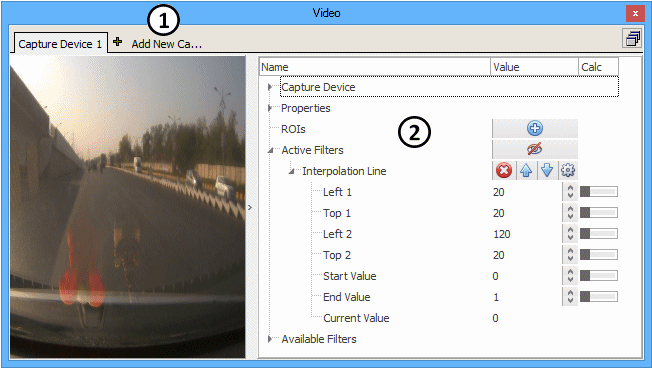
Click Add New Camera (Figure 1:) to add a camera and select the appropriate type.

Capture Device Setup

To begin using a capture device, click on Device Name in the upper right corner and select the camera from the list. If the camera does not appear on the list, verify it is connected to the PC and that Windows recognizes it. Width and Height should be set to the camera's video resolution, in pixels. After a camera is selected, start the live video by taking Vehicle Spy with ICS hardware. Any brand-specific camera settings, if available, can be changed by clicking the cog wheel button labeled Settings after taking Vehicle Spy online.

Axis Network Camera Setup

Note: Ethernet must be enabled in Vehicle Spy to communicate with Axis network cameras. To do this, go to the -> , and check the box in the bottom left corner named "Use PC Ethernet interface.". Vehicle Spy must be restarted after changing the ethernet setting. If multiple Ethernet interfaces exist, use the screen to select the interface connected to the camera.

General Layout and Use of the Video View

Properties

The Description of the video stream changes the labels on the Video view tabs, Expression Builder/Camera sources, and Graphical Panels/Video tools.

Video filters will work while Vehicle Spy is running in simulation mode only if Filters Enabled in Simulation Mode is ON.

ROIs (Regions of Interest)

Regions of Interest can be used to apply filters only to a specific part of the image. Create an ROI by clicking the blue plus button next to the menu item labeled "ROIs". Change its dimensions using the Top, Left, Bottom, and Right fields, or by clicking and dragging on its corners in the video portion of the view. Filters added to the ROI will only affect the portion of the image covered by the ROI.

Active and Available Filters

Filters are used to modify the video in real-time. Active Filters show which ones are currently being applied to the video. Available Filters lists all filters to pick from. To apply a filter, find it in the Available Filters branch then click on its blue plus button. The filter will get added to the Active Filter branch and applied immediately to the video.

Multiple filters can be added to change the entire video image and numerous ROI areas. As a result, be extra careful to verify the filters are on their correct branches because all of them are named Active Filters and Available Filters!

Active filters located higher up in the tree are applied BEFORE active filters located below them

Vehicle Spy uses the Open Source Computer Vision Library (OpenCV) for its video filter algorithms.

Recording Video Using Video View

The Video tab requires the correct VSB file and a folder named Video\Cam_<1-8>\JPEG at the same location. Use the following steps to record video using Video view:

  1. Verify ICS h/w and a camera are connected to the PC.

  2. Verify ICS h/w is also connected to a physical network.

  3. Verify ICS h/w has transmit or receive messages at a rate <= 10 ms.

  4. On Video view, add a capture camera with Logging = ON.

  5. Take VSpy online, capture some video for awhile, then go offline. See the Data directory has a new folder named Video Capture + date stamp\Cam_1\JPEG.

  6. Rename the "Video Capture " folder to just "Video".

Descriptions of All Video Settings

Table 1: Vehicle Spy Video Settings

Video Setting
Description

Capture Device

Camera connected to the PC's USB port or a built-in laptop camera.

Device Name

Camera name determined by the setup in the PC operating system.

Width & Height

Video resolution of the capture camera.

Settings

Custom settings that depend upon which brand of capture camera is being used.

Axis® Network Camera

Axis camera connected to the PC's ethernet network.

IP Address

IP address of the network camera. The default for Axis cameras is 192.168.0.90.

Resolution

Video resolution of the network camera.

FPS

Maximum Frames Per Second allowed for the network camera.

Compression

Compression level of the network camera. A low value gives higher image quality, but also uses more bandwidth and makes larger file sizes.

Camera Number

A number to identify the camera within a group of cameras.

Request URI

Determines the image format by using a request Uniform Resource Identifier (URI) string as defined per Axis API specifications. The default string in Vehicle Spy is: /mjpg/video.mjpg

Properties

Various settings for the Video view.

Description

Description of the video stream used across Vehicle Spy. (Video tab labels, Expression Builder/Cameras, Graphical Panels/Video)

Filters Enabled in Simulation Mode

Use Logged Frames in Simulation Mode (use Video Frames Review instead)

Use video input from replayed frames instead of the attached camera. Use Video Frames Review instead.

Logging

If enabled, each captured frame will be saved as a JPG image in a folder named "Video Capture" in the Data directory. This feature works only if Vehicle Spy is online with ICS hardware.

ROIs

Regions of Interest where filters can be applied to specific image areas.

Description

Description of the region of interest.

Top / Left / Bottom / Right

Defines the boundaries for the region of interest.

Active Filters

Filters being applied to only the ROI area.

Available Filters

List of filters that can be applied to the ROI area.

Active Filters

Toggles ALL filters on/off for the entire image, including any ROI areas. Filters can be added and edited at any time, but can be deleted and moved only if Vehicle Spy is offline. Active filters located higher up in the tree are applied BEFORE filters located below them.

Available Filters - Smoothing

Filters that reduce image noise at the expense of image detail. Image pixels are updated by running a mathematical processing window across them. The filter selection defines the math involved. The Kernel Size defines the size of the processing window or "neighborhood".

Blur

Smooths an image, including any edges found within it. Each pixel is the mean (i.e. average) of its kernel neighbors. Neighboring pixels contribute with equal weight.

Gaussian Blur

Better than the Blur filter at keeping distinct edges. Each pixel is the Gaussian mean of its kernel neighbors. Distant pixels contribute less than nearby pixels as defined by the size of the Gaussian curve.

Median Blur

Better than the Gaussian Blur filter on images with lower noise. Each pixel is the median (i.e. center value in a sorted list) of its kernel neighbors. Neighboring pixels contribute with equal weight.

Bilateral Filter

Better than many filters at reducing noise while keeping sharp edges. Each pixel is a complex weighted average of its kernel neighbors. Neighboring pixels contribute with unequal weight based upon distance and intensity.

Available Filters - Morphology

Filters that use shapes to help isolate or join closely separated areas in the image.

Erosion

Reduces the size of bright areas within an image.

Dilation

Increases the size of bright areas within an image.

Flip

Flips the image vertically, horizontally, or in both directions.

Available Filters - Color/Thresholding

Filters to help isolate colors, intensities, and edges in the image.

Color

Converts the image from one color model to another. Each color model defines a color differently using channels in this order:

  • BGR - Blue, Green, Red.

  • Gray - Single channel of grayscale intensity.

  • YCbCr - Y (brightness), Cb (chroma blue difference), Cr (chroma red difference).

  • HSV - Hue, Saturation, Value (brightness).

In Range

Isolates a specified color range in the image. Pixels "In Range" across all 3 channels become white, and those not within all 3 ranges become black. This filter is good for converting color images into grayscale images to allow Calculation filters to be used afterwards. Channels 0/1/2 correspond to color model channels like blue, green, and red for BGR. Lower/Upper sets the color range boundaries for the given channel.

Threshold

Isolates a specified intensity range in the image. Threshold - pixel intensity threshold where a logic decision is made depending upon the chosen Type.

Max Value - maximum pixel intensity for the Binary and Binary Inverse Types.

Edges

Shows edges in the image as white lines on a black background by using the "Canny Edge Detector" algorithm. Threshold - sets the lower hysteresis threshold for the algorithm.

Available Filters - Calculation

Filters that show results of various calculations; these filters do not change the image. All of these filters work only on grayscale images.

Moments

Image moments can be used to determine the area, center point, and orientation of an object within an image; but only after the object has been isolated with filtering. This filter works only on grayscale images. The moments are shown as various weighted averages of pixel intensities. For a well defined object, moment values can be used in further calculations like these: Object area = Spatial 00 Object center point X = Spatial 10 / Spatial 00 Object center point Y = Spatial 01 / Spatial 00

Find Line

Calculates the XY coordinate endpoints for one best fit line using the "Progressive Probabilistic Hough Transform". This filter works only on grayscale images. The line is found by spinning a voting accumulator of length ρ at increments of angle θ across the image from a point of origin. XY coordinates are given for the line with the most votes that is also long enough and has minimal gaps. <Inputs> Distance Resolution ρ - distance resolution of the accumulator, in pixels. Angle Resolution θ - angle resolution of the accumulator, in radians. (1 deg = 0.0174533 radians) Threshold - vote threshold to meet before a line is detected. Min Line Length - minimum length of the line, in pixels. Max Line Gap - maximum allowed gap between points within the line, in pixels. <Outputs> Left 1 - X coordinate of best fit line endpoint #1 Top 1 - Y coordinate of best fit line endpoint #1 Left 2 - X coordinate of best fit line endpoint # Top 2 - Y coordinate of best fit line endpoint #2

Count Non Zero

Counts the total number of pixels that have an intensity > 0. This filter works only on grayscale images.

Min Max Location

Finds the XY coordinates of the darkest and brightest pixel. This filter works only on grayscale images. Min Left - X coordinate of darkest pixel Min Top - Y coordinate of darkest pixel Max Left - X coordinate of brightest pixel Max Top - Y coordinate of brightest pixel

Interpolation Line

Finds the brightest spot along a line and reports that spot's location as a value between two endpoint values. If multiple pixels in the line have the same brightness, it reports the pixel location with the lowest value. This filter works only on grayscale images. <Inputs> Left 1 - X coordinate of line start point Top 1 - Y coordinate of line start point Left 2 - X coordinate of line end point Top 2 - Y coordinate of line end point Start Value - value at line start point End Value - value at line end point <Output> Current Value - location of the bright spot along the line with its range defined by the Start and End Values.

Interpolation Arc

Finds the brightest spot along an arc and reports that spot's location as a value between two endpoint values. If multiple pixels in the arc have the same brightness, it reports the pixel location with the lowest value. The arc radius is defined using an outline box with a point of origin in its center. The arc length is defined with start and end angles. This filter works only on grayscale images. <Inputs> Left 1 - X coordinate of box corner #1 Top 1 - Y coordinate of box corner #1 Left 2 - X coordinate of box corner #2 Top 2 - Y coordinate of box corner #2 Start Angle - angle of the arc start point, in degrees. End Angle - angle of the arc end point, in degrees. (0 deg = right, 90 deg = down, 180 deg = left, 270 deg = up) Start Value - value at arc start point End Value - value at arc end point <Output> Current Value - location of the bright spot along the arc with its range defined by the Start and End Values.

Available Filters - Drawing

Tools for drawing new objects on the image.

Text

Places text on the image according to the various settings provided.

Line

Places a line on the image according to the various settings provided.

To begin using the Axis network camera, enter its IP Address in the upper right corner. The default IP address for Axis cameras is 192.168.0.90. Note that the PC must be on the same subnet as the Axis network camera. Various settings can be changed like FPS (Frames Per Second), Compression, and Camera Number (if more than one). The Request URI text string should be set to /mjpg/video.mjpg. After the Axis camera is set up, start the live video by taking Vehicle Spy with ICS hardware.

A tab for each camera is shown across the top. Live video from the chosen camera is shown on the left. A tree view along the right (Figure 1:) has settings for the chosen camera and also shows the outputs of Calculation filters. Expand and collapse tree branches by clicking on the little triangles. Add items to the tree by clicking on their blue plus button. Delete items by clicking on their red X button. Move items up and down in the tree by clicking on their blue up and down arrows. Items can be added and edited at any time, but can be deleted and moved only if Vehicle Spy is offline.

Some inputs have a horizontal on/off switch on their right side to change between manual and modes. Some outputs have a cog wheel to open a dialog to change the format and units displayed across Vehicle Spy.

If Logging is enabled then each captured frame will be saved on the PC as a JPG image in a date stamped folder named "Video Capture" in the . This feature works only if Vehicle Spy is online with licensed ICS hardware.

On Messages view, manually as a VSB file.

Allows video filters to work while Vehicle Spy is running in .

online
calculated signal
Data directory
save the buffer
simulation mode
Measurement menu
Video Tab
Graphical Panels
Expression Builder
online
Tools
Options
Spy Networks tab
Logon
Figure 1: Record and analyze live video streams with the PC using Video view.