VSpy 3 Documentation
All DocsProductsLearning CenterSupport
3.9.13
3.9.13
  • 🚗Welcome to the Vehicle Spy Help Documentation
  • Vehicle Spy Introduction
    • Vehicle Spy Overview
      • Vehicle Spy Tour
        • Vehicle Spy Tour 1: Bus Monitor
        • Vehicle Spy Tour 2: Signal Monitoring and Recording
        • Vehicle Spy Tour 3: Flight Recording
        • Vehicle Spy Tour 4: Node/Vehicle Simulation
        • Vehicle Spy Tour 5: Test Automation
        • Vehicle Spy Tour: Summary
    • Other Vehicle Spy Users
    • Vehicle Spy Specifications
    • Vehicle Spy Required Hardware PC System Requirements
    • Vehicle Spy Website
  • Vehicle Spy Tutorials
    • Vehicle Spy Tutorial Files
    • Getting Comfortable with the User Interface
    • Tabs in the User Interface
    • Tutorial 1: Basics of Vehicle Spy
      • Part 1 - Logon Screen
      • Part 2 - Monitor Message Traffic
      • Part 3 - Examine Messages
      • Part 4 - Your Message Specification in Action
      • Part 5 - Filtering Messages
      • Part 6 - More Ways to Filter in Vehicle Spy
      • Part 7 - Message Timestamps and Pausing
      • Part 8 - Save Your Messages View Buffer
      • Part 9 - Clear the Messages View Buffer
      • Part 10 - Exercises
    • Tutorial: Transmit Messages with Vehicle Spy
      • Part 1 - Load the Setup File
      • Part 2 - Enter a Transmit Message
      • Part 3 - Utilize the Alternate Workspace Panels
      • Part 4 - Manually Transmit a Message
      • Part 5 - Periodically Transmit a Message
      • Part 6 - Automatically Respond to a Message
      • Part 7 - Exercises
    • Tutorial: Decode Signals from Messages
      • Part 1 - Load a Setup File
      • Part 2 - Enter a Message
      • Part 3 - Enter an Equation for an Analog Value
      • Part 4 - View Message Data
      • Part 5 - View Message Data with the Signal List and Signal Plot
      • Part 6 - An Introduction to Signal Plot Features
      • Part 7 - Exercises
    • Tutorial: Database Setup
      • Part 1 - Platform Overview
      • Part 2 - Create a Platform
      • Part 3 - Adding Database Files
      • Part 4 - ECU Setup Wizard
      • Part 5 - Diagnostic Decoding
      • Part 6 - Conclusion
    • Tutorial: Basics of Capture Function Block and Graphical Panels
      • Part 1 - Setup the Simulation
      • Part 2 - Setup the Capture Function Blocks
      • Part 3 - Setup the Graphical Panel
      • Part 4 - Conclusion
    • Tutorial: Basics of Scripting and Playback
      • Part 1 - Setup Application Signals
      • Part 2 - Setup the Graphical Panel
      • Part 3 - Setup The Playback Function Block
      • Part 4 - Setup the Script Function Block
      • Part 5 - Summary
    • Tutorial: Request and Save DTC Data
      • Part 1 - Create a Diagnostic Job
      • Part 2 - Create Function Block to Request and Save Data
      • Part 3 - Make a Graphical Panel
      • Part 4 - Request, Save, and View the DTCs
      • Part 5 - Conclusion
    • Tutorial: DPS Programming Automation
      • Part 1 - Create DPS Programming Job
      • Part 2 - Create Function Block to Launch Programming Services
      • Part 3 - Make a Graphical Panel
      • Part 4 - Use the DPS Programming Graphical Panel
      • Part 5 - DPS Programming Automation Conclusion
    • Tutorial: Getting Fancy with Diagnostics
      • Part 1 - Read Data By Identifier Setup
      • Part 2 - Write Data by Identifier Setup
      • Part 3 - Writing the Read DID
      • Part 4 - Request Identifiers using Dynamically Define Data Identifier
      • Part 5 - Request the Dynamic Identifier
      • Part 6 - Conclusion
    • Tutorial: Sort Messages by ECU
      • Part 1 - Start a New Vehicle Spy Application
      • Part 2 - Enter ECU Source IDs to Sort
      • Part 3 - Setup Capture Type Function Blocks
      • Part 4 - Sort the ECU Messages
      • Part 5 - Setup Application Signals
      • Part 6 - Setup Playback Type Function Blocks
      • Part 7 - Setup Script Type Function Blocks
      • Part 8 - Construct a User Dialog
      • Part 9 - Run the Setup
    • Tutorial: Configuring and Using CoreMini
      • Part 1 - Creating a Tx Message
      • Part 2 - Logging Data
      • Part 3 - Loading the Script to the Hardware
      • Part 4 - How to Run the Script
      • Part 5 - Extracting Data
      • Part 6 - Viewing the Data
      • Part 7 - Conclusion
    • Tutorial: Simple Standalone Logging
      • Part 1 - Getting Started
      • Part 2 - Database/Hardware Setup
      • Part 3 - Channels
      • Part 4 - Checking Channel Selection
      • Part 5 - Standalone Logging
      • Part 6 - CoreMini Console
      • Part 7 - Extract Data
      • Part 8 - Conclusion
    • Tutorial: Standalone Video Logging
      • Tutorial: Standalone Video Logging - Part 1 - Setting up the Axis Camera
      • Tutorial: Standalone Video Logging - Part 2 - Setting Up Vehiclescape DAQ
      • Tutorial: Standalone Video Logging - Part 3 - Extracting the Video
    • Tutorial: C Code Interface
      • Part 1 - Create a Project
      • Part 2 - Adding Events
      • Part 3 - Running the Example
      • Part 4 - Debugging
      • Part 5 - Conclusion
    • Tutorial: How to run multiple devices in one VS3 file
      • Part 1 - Enabling Multiple Devices
      • Part 2 - Adding Devices
      • Part 3 - Assigning Devices
      • Part 4 - Syncing Time Across Multiple Devices
  • Tutorial Summary
  • Basic Operation of Vehicle Spy
    • The Logon Screen
    • Menus & Buttons
    • Running and Stopping
    • Data Directory
    • Create, Open, & Save Vehicle Spy Setups
    • Alternate Workspaces
    • Using Window Docking
  • Vehicle Spy Main Menus
    • Main Menu: File
      • The Logon Screen
      • Create, Open, & Save Vehicle Spy Setups
      • Import Function Blocks and Graphical Panels
      • Data Directory
      • Review Buffer
    • Main Menu: Setup
      • Setup a Network
      • Setup Platforms
      • Network Databases
      • ECUs View
        • Edit ECU Diagnostic Database
        • ECU Diagnostic Services Tab
      • Data Cache Disk Streaming
    • Main Menu: Spy Networks
      • Snapshot
      • Messages View
        • Messages View Filter Bar
          • Messages View Custom Filters
        • Messages View Top Toolbar
          • Message Details Pane
          • Reverse Engineering
          • Messages View Timestamping
          • Pause Messages View
          • Save the Buffer
          • Clear the Buffer
        • Messages View Column Headers
        • Messages View Column Filters
        • Messages View Buffer Display
          • Displaying Signals in Messages View
          • Buffer Progress Display
          • Messages View Task Menus
        • Messages View Bottom Toolbar
          • Color Filters
          • Messages View Data Byte Format
          • Messages View Setup
      • Message Editor
        • Messages Editor: Overview
        • Messages Editor: Receive, Transmit, & Database Tables
        • Add and Delete Messages
        • Messages Editor: Cut, Copy, and Paste
        • Messages Editor: Sort and Arrange
        • Messages Editor: Pick a Network
        • Messages Editor: Right Click Menu
        • Message PT, Trgt, and Src
        • Messages Editor: Message Fields
          • Message Key
          • Message Description
          • Message Type
          • Message Arbitration ID
          • Multiframe Message
            • Receive ISO15765-2 Multiframe Message
            • Transmit ISO15765-2 Multiframe Message
          • Message Length
          • Message Data Bytes
            • Transmit Long Messages
          • Message Source Node
          • Receive Message "Tx Msg" Field
          • Message Color
        • Message Signals
          • Live Edit
          • Message Signal Type
          • Message Signal Type Analog
          • Message Signal Type Digital
          • Message Signal Type State Encoded
          • Message Signal Type Text
          • Message Signal Type DTC
          • Understanding Bit and Byte : Bit Positions
          • Message Signal Format and Units
      • Transmit Panel
        • Ways to Transmit Messages
          • Auto Tx and Transmit Rate
        • Add and Delete Transmit Messages
        • Transmit Panel Filter Bar
        • Dynamic Transmit Message Bytes
      • Networks
        • Setup a Network
        • Network Statistics
        • Moving Messages Between Networks
      • TCP/IP
      • FlexRay Controllers
        • FlexRay Controllers: State/Action Tab
        • FlexRay Controllers: Configuration Tab
        • FlexRay Controllers: Registers Tab
      • FlexRay Cycles
      • Diagnostics
        • Diagnostics View
        • Diagnostics Setup
      • Diagnostics over IP (DoIP)
      • Simulator
      • ECUs View
        • GMLAN ECUs
        • ISO 14229 ECUs
        • Keyword 2000 ECUs
    • Main Menu: Measurement
      • VehicleScape DAQ
        • VehicleScape DAQ: Database/Hardware Setup Tab
        • VehicleScape DAQ: Channels Tab
        • VehicleScape DAQ: PC Logging Tab
        • VehicleScape DAQ: Standalone Logging Tab
          • Standalone Logging: Collections and Methods
            • Collections and Methods: Message Capture Method
              • Message Capture Method: Message Collection Options
              • Message Capture Method: Start Options
            • Message Capture Method: Stop Options
              • Message Capture Method: Stop Options: Finish After Collecting Messages or When Expression is True
              • Message Capture Method: Stop Options: Pre/Post Collection
              • Message Capture Method: Stop Options: One Shot Report
            • Message Capture Method: Restart Options
            • Message Capture Method: Upload to Wireless neoVI
            • Collections and Methods: Bus Query Method
            • Collections and Methods: Histogram Method
            • Collections and Methods: Ethernet DAQ Method
          • Standalone Logging: Status Reporting
          • Standalone Logging: Power Management
          • Standalone Logging: Generation Options
        • VehicleScape DAQ: Gateway
        • VehicleScape DAQ: Online Tab
      • Signal Views
        • Signal Plot
        • Signal List
      • Graphical Panels
        • Graphical Panels: Tools
          • Graphical Panel Controls: Common Control Properties
          • Graphical Panel Controls: LED
          • Graphical Panel Controls: Text Display
          • Graphical Panel Controls: Meter
          • Graphical Panel Controls: Function Block Button
          • Graphical Panel Controls: Tx Button
          • Graphical Panel Controls: On/Off Button
          • Graphical Panel Controls: Action Button
          • Graphical Panel Controls: Diag Job Action Button
          • Graphical Panel Controls: Bargraph
          • Graphical Panel Controls: Knob
          • Graphical Panel Controls: Grid
          • Graphical Panel Controls: Numeric Entry
          • Graphical Panel Controls: Graph
          • Graphical Panel Controls: Text Entry
          • Graphical Panel Controls: Graphical Display
          • Graphical Panel Controls: Drop Down List
          • Graphical Panel Controls: Message History
          • Graphical Panel Controls: Flash Control
          • Graphical Panel Controls: Radio Button
          • Graphical Panel Controls: Bitmap Button
          • Graphical Panel Controls: Panel Button
          • Graphical Panel Controls: Hex Edit
        • Graphical Panels: Add or Delete a Tool
        • Graphical Panels: Tool Properties
        • Graphical Panels: Move a Tool
        • Graphical Panels: Resize a Tool
        • Graphical Panels: Format (Align or Resize) a Tool Group
        • Graphical Panels: Add or Delete Panels
        • Graphical Panels: Select and Work With Panels
        • Graphical Panels: Panel Properties
        • Graphical Panels: Lock Panels
        • Floating Panels
      • Logging
      • MEP (XCP/CCP) - Memory Edit Protocol
        • MEP Setup
          • MEP Setup - Properties
          • MEP Setup - Import / Export
          • MEP Setup - DAQ Tables
          • MEP Setup - Security
          • MEP Setup - Memory / Hex / S19
        • MEP Value Editor
        • MEP Curve Editor
        • MEP Map Editor
        • Data Acquisition with CCP/XCP
      • Data Analysis
        • Data Analysis: Main Menus and Toolbar
        • Data Analysis: Zoom Toolbar
        • Data Analysis: X-Axis Input Toolbar and Dialog
        • Data Analysis: Plotter Setup Toolbar
      • Data Analysis: Tool Dialog
        • Data Analysis: Calculated Channels
      • Data Analysis: Plotter Area
        • Data Analysis: Plotter Options
        • Data Analysis: Advanced Plotting Methods
      • Data Analysis: Channel Value Pane
      • Data Analysis: Output Bar
      • GPS Maps
      • Video
    • Main Menu: Embedded Tools
      • DPS Archive Viewer
      • CAN Terminal
      • Intrepid ECU Flasher: Definitions
      • J1939 Address Manager
      • J1939 DTC Monitor
      • BitSmash
    • Main Menu: GMLAN
      • Virtual Networks
      • GM CGI Bus
    • Main Menu: Scripting and Automation
      • Function Blocks
        • Function Blocks Toolbar
        • Function Block List
        • Function Block Start Tab
        • Function Blocks Types
          • Script Type Function Block
          • Script Type Function Block: Script Toolbar
          • Script Type Function Block: Commands
            • Script Type Function Block Command: Clear History
            • Script Type Function Block Command: Clear Stats
            • Script Type Function Block Command: Comment
            • Script Type Function Block Command: CoreMini Action
            • Script Type Function Block Command: DAQ Action
            • Script Type Function Block Command: Diag Job Action
            • Script Type Function Block Command: Function Block Action
            • Script Type Function Block Commands: If, Else, Else If, End If
            • Script Type Function Block Command: Jump If
            • Script Type Function Block Command: Jump To
            • Script Type Function Block Command: Load Message Data
            • Script Type Function Block Command: Log Data
            • Script Type Function Block Commands: Start Loop and End Loop
            • Script Type Function Block Command: Pause
            • Script Type Function Block Command: Read Data
            • Script Type Function Block Command: Set Value
            • Script Type Function Block Command: Set Value If
            • Script Type Function Block Command: Show Panel
            • Script Type Function Block Command: Sleep
            • Script Type Function Block Command: Stop
            • Script Type Function Block Command: Test DTC
            • Script Type Function Block Command: Text API
            • Script Type Function Block Command: Transmit
            • Script Type Function Block Command: Wait For
            • Script Type Function Block Command: Wait Until
          • Script Type Function Block: Resetting the Present Flag
          • Script Type Function Block: Debugging Tools
          • Capture Type Function Block
            • Capture Type Function Block: Filter Tab
            • Capture Type Function Block: Stop and Trigger Tab
            • Capture Type Function Block: Storage Tab
            • Capture Type Function Block: Data Tab
          • Playback Type Function Block
          • Function Blocks Hotkeys
      • C Code Interface
        • Working with the C Code Interface
        • C Code Interface: Functions and Events
          • Functions and Events: Message Objects
          • Functions and Events: Application Signals
          • Functions and Events: Timers
          • Functions and Events: Common Functions and Events
          • Functions and Events: Graphical Panels
          • Functions and Events: Diagnostic Jobs
          • Functions and Events: Function Blocks
          • Functions and Events: Text API
          • Functions and Events: Network Indexes and Statistics
        • C Code Interface: Object Names, Debugging, and Common Mistakes
        • C Code Interface: Advanced Topics
        • C Code Interface: CAPL Conversion
      • Application Signals
        • Application Signals: Save and Restore
      • Text API Terminal
    • Main Menu: Run
    • Main Menu: Tools
      • Utilities: CoreMini Console
        • Utilities: CoreMini Control
        • Utilities: CoreMini Partitions
        • Utilities: CoreMini Advanced Settings
      • Utilities: Extract / Export
        • Utilities: Extract from SD Card
        • Utilities: Export VSB to Other Formats
        • Utilities: Export VSB Convert VSB (with VSDB) to Other Formats V using Command Prompt in Windows
        • Utilities: Export VSB to CSV format using DataExtract.exe
      • Tools: Problem Log
      • Utilities: File Conversions
        • VSB Editor
      • Tools: Utilities
        • Utilities: VS3EXE Generator
        • Utilities: Hardware Acceleration
        • Tools: Performance
        • Tools: Language
      • PLASMA / ION Setup
      • Tools: Options
        • Options: Spy Networks Tab
          • Spy Networks Tab: J1850 VPW Mode
        • Options: Performance Settings
        • Options: Multimedia
          • Multimedia: Joystick Setup
        • Options: Text API Options
        • Options: License System
          • License Upgrade Eligibility
        • Options: GPS Setup
        • Options: Data Directories
        • Options: Regional Settings
    • Main Menu: Help
      • Contact Information - Intrepid Control Systems, Inc.
      • Vehicle Spy Website
  • Shared Features in Vehicle Spy
    • Shared Features: Calculated Signal Editor
      • Shared Features: Calculated Analog or Digital Signals
      • Shared Features: Calculated Text Signals
    • Shared Features: DTC Database
    • Shared Features: Expression Builder
    • Shared Features: Predefined Function Keys
    • Shared Features: Starting with a Selected View
    • Shared Features: Widgets
  • Vehicle Network Interface Hardware
    • Vehicle Network Interface Hardware: neoVI FIRE
      • General Purpose IO
    • Vehicle Network Interface Hardware: neoVI RED
    • Vehicle Network Interface Hardware: neoVI Blue
      • General Purpose IO
    • Vehicle Network Interface Hardware: ValueCAN
    • Getting Started with neoECU
      • neoECU Requirements
      • neoECU 10
        • neoECU 10: IO Map
        • neoECU 10: Loading Scripts Over CAN
        • neoECU 10: Power Up and Buttons
        • neoECU 10: Examples
      • neoECU 20
        • neoECU 20: Configuration
        • neoECU 20: IO Map
        • neoECU 20: Loading Scripts Over USB
        • neoECU 20: Examples
      • neoECU Firmware Updates
      • neoECU Sleep Mode
    • Vehicle Spy Text API
      • Vehicle Spy Text API: ECU Object
      • Vehicle Spy Text API: Labview Interface
    • Vehicle Spy VSB file Spec
  • Application Notes
    • Application Note: CoreMini Partition Logging
      • Logging - Part 1: General Setup
      • Logging - Part 2: Function Block Setup
      • Logging - Part 3: Sending the Script to the Hardware
      • Logging - Part 4: Conclusion
    • Application Note: VehicleScape Standalone Logging
      • Application Note: VehicleScape Standalone Logging - Part 1: Message Collection Options
      • Application Note: VehicleScape Standalone Logging - Part 2: Collection and Restart Options
      • Application Note: VehicleScape Standalone Logging - Part 3: Reporting Options, Power Management and
      • Application Note: VehicleScape Standalone Logging - Part 4: neoVI MOTE Setup
    • Application Note: XCP Driver Example
      • Application Note: XCP Driver Example - Part 1: Process Overview
      • Application Note: XCP Driver Example - Part 2: Example XCP Driver
      • Application Note: XCP Driver Example - Part 3: ECU Simulation and Porting XCP Driver
    • Application Note: neoVI Logging neoECU DAQ
      • Application Note: neoVI Logging neoECU DAQ - Part 1: neoECU Setup
      • Application Note: neoVI Logging neoECU DAQ - Part 2: VehicleScape DAQ
      • Application Note: neoVI Logging neoECU DAQ - Part 3: Review Data
    • Application Note: Using the neoVI MOTE
      • Application Note: Using the neoVI MOTE - Part 1: Messages
      • Application Note: Using the neoVI MOTE - Part 2: Display on Screen
      • Application Note: Using the neoVI MOTE - Part 3: Using the Speaker
      • Application Note: Using the neoVI MOTE - Part 4: Home Screen and Conclusion
    • Application Note: Gateway Builder Tutorial
      • Tutorial - Gateway Builder - Part 1 - Intro
      • Tutorial - Gateway Builder - Part 2 - Gateway Builder Overview
      • Tutorial - Gateway Builder - Part 3 - Add Messages to Gateway Builder
      • Tutorial - Gateway Builder - Part 4 - Gateway Input Actions
      • Tutorial - Gateway Builder - Part 5 - Output Messages, Signals, and Triggers
    • Application Note: Dynamically Manipulating Application Signal Arrays
      • Application Note: Dynamically Manipulating Application Signal Arrays
      • Application Note: Dynamically Manipulating Application Signal Arrays
      • Application Note: Dynamically Manipulating Application Signal Arrays
      • Application Note: Dynamically Manipulating Application Signal Arrays
    • PHY Dashboard
    • Sample Replay Files
  • Contact Us
    • Contact Information - Intrepid Control Systems, Inc.
Powered by GitBook
LogoLogo

Applications

  • Cybersecurity
  • Data Logging
  • Simulate ECU Functions
  • Diagnostics, Testing and Validation

Products

  • Vehicle Network Adapters
  • Data Loggers
  • Software
  • Automotive Ethernet Tools

Support

  • Support Resources
  • Contact Support
  • Class Schedule & Registration
  • Training Video Library

Company

  • About
  • News
  • Events
  • Contact Us

Copyright © 2024 | All Rights Reserved

On this page
Edit on GitHub

The State/Action tab is where the two FlexRay coldstart nodes within ICS hardware can be controlled and monitored. The tab is divided into Options, actions, and a node status table as shown in Figure 1.

Remember to select the correct Network above the tab before using any of the features.

Page navigation aids are included here to help with the long page length:

**** **** ****

Options

Table 1: State/Action Options

FlexRay Wakeup and Coldstart

FlexRay wakeup and coldstart can be confusing, so they are explained further here.

A FlexRay cluster is a collection of at least two coldstart nodes and usually some non-coldstart nodes too. Coldstart nodes can start or join FlexRay cycling, but non-coldstart nodes can only join cycling.

FlexRay cycling begins if at least two coldstart nodes are awake and then one of them does a coldstart A node wakeup can come from an external trigger OR from a FlexRay wakeup sent by a coldstart node. A FlexRay wakeup is a pattern of at least two wakeup symbols sent on only one channel at a time. The entire cluster of nodes will wake up after detecting a FlexRay wakeup pattern on their wakeup channel, assuming the nodes were not already awake from their external triggers.

Cluster Action

Table 2: Cluster Actions

Node Action

There are many choices for a Node Action as described in Table 3 and most of them refer to specific controller states. Actions at this lower level are not usually needed unless trying to troubleshoot specific issues.

It is strongly recommended to refer to state transition diagrams in the FlexRay Protocol 2.1A specification when using these node actions.

Table 3: Node Actions

State/Action Status Table

For each node, the status table shows the current logic state and timing location within the overall FlexRay cycle schedule. The status table also allows an ECU from a FlexRay database to be assigned to a node.

Table 4: State/Action Table

POC States

There are many Protocol Operation Control states that define FlexRay logic in a node. It is strongly recommended to refer to state transition diagrams in the FlexRay Protocol 2.1A specification when trying to understand the flow of these states.

A lookup table is included here for convenience, but this does not replace requirements from specifications. Most of this information is copied directly from the FlexRay 2.1A specification then edited for brevity. The states are listed alphabetically.

Table 5: POC States

Page navigation aids are included here to help with the long page length:

The Options area (Figure 1:) includes some startup and synchronization settings. Additional options for synchronizing to a database are located at the bottom of the tab.

State/Action Option
Description

ICS FlexRay hardware comes with two built-in nodes that can act as a simple cluster by itself or can be connected to a larger cluster of nodes. The cluster inside ICS hardware can be controlled on the State/Action tab by executing a Cluster Action (Figure 1:) while Vehicle Spy is online.

Cluster Action
Description

To perform a Node Action, select a node by highlighting its row in the status table, select a Node Action (Figure 1:), then click Execute to perform the selected action on the highlighted node.

Node Action
Description

Each row in the status table (Figure 1:) represents one node in the ICS FlexRay hardware. A Vehicle Spy Cluster Action affects both nodes, but a Node Action only affects the selected node in the table.

State/Action Status Column
Description
POC State Name
Description

**** **** **** **** ****

  1. Vehicle Spy Main Menus
  2. Main Menu: Spy Networks
  3. FlexRay Controllers

FlexRay Controllers: State/Action Tab

PreviousFlexRay ControllersNextFlexRay Controllers: Configuration Tab
  • Options
  • FlexRay Wakeup and Coldstart
  • Cluster Action
  • Node Action
  • State/Action Status Table
  • POC States
Top of Page
Options
Actions
Status Table
States

Startup upon going online

On - ICS hardware will be the "leading coldstart node", so it will coldstart the FlexRay cluster after going online with VSpy. Off - ICS hardware will be a "following coldstart node", so it will begin in a listen state after going online with VSpy. A startup from an external FlexRay node is needed before frames will appear.

Wakeup before startup

Sync node frames to database upon change

Start

Forces the ICS hardware cluster to coldstart, which can also get an external cluster to begin cycling if the external cluster is already awake.

Stop

Forces the ICS hardware cluster to stop cycling, but this will not stop an external cluster that is already cycling.

Restart

Stops the cluster first before doing a Start.

Reconfigure and Restart

Start

Forces node to coldstart.

Stop

Forces node to stop cycling. If POC state is NORMAL_ACTIVE then forces node to stop after the current cycle is done. (i.e. Halt) If POC state is not NORMAL_ACTIVE then forces node to immediately stop even if the current cycle is not done yet. (i.e. Freeze)

Restart

Stops the node first before doing a Start.

Reconfigure and Restart

Set POC to Config

(POC means Protocol Operation Control, which is the FlexRay state control logic within the node.) Forces node state to DEFAULT_CONFIG or CONFIG depending upon when this action is attempted. Values are NOT configured until Node Action Perform Config of CHI and Msg Bufs is done.

Set POC to Ready

Forces node to be ready to send a wakeup, begin a coldstart, or jump into a cycling cluster.

Set POC to Wakeup

Forces node to send a wakeup pattern as defined on the Configuration tab.

Set POC to Monitor

Forces node to monitor for wakeups and cycling, but not send any frames itself.

Set POC to Halt

Forces node to stop cycling after the current cycle is done.

Set POC to Startup

Forces node to coldstart an inactive cluster or jump into a cycling cluster.

Set POC to Run

Forces a ready node to startup, otherwise does nothing.

Set POC to Freeze

Forces node to immediately stop cycling even if the current cycle is not done yet.

Set POC to Send MTS

Forces node to send a Media Access Test Symbol. The MTS is sent within a Symbol Window which is a cycle segment defined on the Configuration tab. Note: An MTS pulse is the same as a Collision Avoidance Symbol (CAS), but MTS is sent within a cycle and CAS is sent outside of a cycle.

Set POC to All Slots

Forces node from single slot mode to all slots mode. Single slot mode is an optional feature to limit frame transmission during startup.

Set POC to Reset Status Indicators

Resets node status flags that track coldstart and wakeup events. This action works only if the POC state is READY or STARTUP.

Set POC to Clear RAMs

Clears all POC related RAM in the node to zero. This action works only if the POC state is DEFAULT_CONFIG or CONFIG.

Perform Config of CHI and Msg Bufs

Key

Unused at this time.

Node Name

POC State

Current state of the FlexRay logic in the node. The many Protocol Operation Control states are described further in a table following this one. The node state can change due to external cluster connections or be changed directly by executing a Cluster or Node Action.

Slot Counter A

Current slot of channel A. Counter resets to 1 at the beginning of each cycle then counts slots across the static and dynamic segments until the end of the dynamic segment is reached.

Slot Counter B

Same counting logic as channel A, but this tracks channel B.

Macroticks

Current macrotick within the current cycle. Counter resets to 0 at the beginning of each cycle.

Cycle Cnt

Current cycle number that loops from 0 to 63.

Rate Fix

Current Rate Correction Value calculated by the node to adjust its macrotick frequency. Allows the node to compensate for internal clock drift and stay synchronized to a cycling cluster.

Offset Fix

Current Offset Correction Value calculated by the node to adjust its macrotick phase. Allows the node to compensate for internal clock drift and stay synchronized to a cycling cluster.

ABORT_STARTUP

Exit cluster startup process for various reasons then get ready to try again by going to STARTUP_PREPARE.

COLDSTART_COLLISION_RESOLUTION

Detect and resolve collisions between multiple simultaneous coldstart attempts of several coldstart nodes.

COLDSTART_CONSISTENCY_CHECK

Leading coldstart node checks whether frames transmitted by other following coldstart nodes fit into its schedule.

COLDSTART_GAP

Leading coldstart node stops transmitting its startup frame. All nodes integrating on leading coldstart node will stop their integration attempt.

COLDSTART_JOIN

Only following coldstart nodes enter this state. Upon entry they begin transmitting startup frames and continue to do so in subsequent cycles.

COLDSTART_LISTEN

Coldstart node tries to detect ongoing frame transmissions and coldstart attempts. A coldstart node still allowed to initiate a coldstart enters this state before actually performing a coldstart.

CONFIG

DEFAULT_CONFIG

Frame communication is stopped, all node configuration memory is accessible, and physical layer pins are set to their inactive state. Default settings "hardcoded" in the firmware are applied.

HALT

Halts the node in preparation for reinitialization.

INITIALIZE_SCHEDULE

This state is entered as soon as a valid startup frame has been received in one of the listen states.

INTEGRATION_COLDSTART_CHECK

Only integrating coldstart nodes pass through this state. Verify clock can be corrected and leading coldstart node is still available.

INTEGRATION_CONSISTENCY_CHECK

Only integrating non-coldstart nodes pass through this state. Verify clock can be corrected and enough coldstart nodes are sending startup frames that agree with the node's own schedule.

INTEGRATION_LISTEN

Node waits for a valid startup frame or for a coldstart to be allowed.

MONITOR_MODE

Node receives wakeups and frames, but does not send any frames itself.

NORMAL_ACTIVE

Normal operation state following a successful startup. Node is synchronized to the cluster allowing continued frame transmission without disrupting other nodes. If synchronization problems occur, POC can transition to NORMAL_PASSIVE.

NORMAL_PASSIVE

Node can receive frames, but not transmit frames due to synchronization problems to the cluster. If synchronization improves, POC can transition back to NORMAL_ACTIVE. If synchronization problems persist, POC transitions to HALT.

READY

Node is ready to send a wakeup, coldstart a cluster, integrate into an ongoing cluster, or be configured again.

STARTUP_PREPARE

Node prepares to listen for cluster activity.

STARTUP_SUCCESS

This seems to not really be a POC state, but is actually a critical flag that must be true to enter the NORMAL_ACTIVE state.

WAKEUP_DETECT

Node attempts to identify reason for wakeup collision detected in WAKEUP_SEND state then returns to WAKEUP_STANDBY.

WAKEUP_LISTEN

Node prepares to quickly send a wakeup in a noise free scenario or waits a bit longer in a noisy environment.

WAKEUP_SEND

Node sends wakeup pattern on wakeup channel defined on the Configuration tab. Node transitions to WAKEUP_DETECT if collisions are detected.

WAKEUP_STANDB

Node is waiting to send a wakeup pattern.

Configuration
FlexRay Controllers
Options
Actions
Status Table
States

Startup upon going online must be ON before this feature will work. On - Each node within ICS hardware will transmit a FlexRay wakeup pattern on its wakeup channel after going online with VSpy, but before it does a coldstart. The wakeup pattern and channel are defined on the tab. A wakeup pattern must have at least two wakeup symbols to be successful. Off - ICS hardware will not send a FlexRay wakeup before doing a coldstart.

This setting can synchronize to the Database frames. On - After selecting an ECU in the Node Name list, all transmit frames assigned to that node are deleted and replaced with all database frames from the ECU. The ECUs and their database frames come from FIBEX or ARMXL files loaded in . Off - Node transmit frames are not forced to be synchronized to a database.

Reconfigures the ICS hardware cluster to the tab cluster settings, then forces the ICS hardware cluster to coldstart.

Stops the node, then reconfigures it to tab node settings, then forces node to coldstart.

Forces node to configure its Controller Host Interface and message buffers. This action works only if the POC state is DEFAULT_CONFIG or CONFIG. If POC state is DEFAULT_CONFIG then settings come from "hardcoded" values stored within ICS hardware. If POC state is CONFIG then settings come from tab, Nodes branch settings.

Name of the node as defined on the tab, Node Settings, ECU Short Name. Also, an ECU can be assigned to the node here if an ECU database from a FIBEX or ARMXL file is already loaded in . This quickly allows ICS hardware to simulate a FlexRay ECU. WARNING: If the option Sync node frames to database upon change is ON then making an ECU selection here will replace all assigned to the node with database frames from the selected ECU.

Frame communication is stopped, all node configuration memory is accessible, and physical layer pins are set to their inactive state. Settings from the tab are applied.

Configuration
Messages Editor Transmit frames
Network Databases
Configuration
Configuration
Configuration
Configuration
Network Databases
transmit frames
Configuration
Figure 1: 
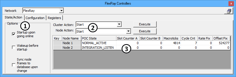
The FlexRay Controllers State/Action tab.