
Tutorial - Gateway Builder - Part 2 - Gateway Builder Overview
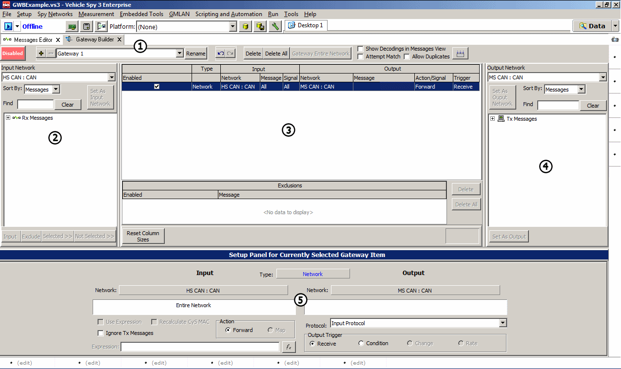
Figure 1:  - Gateway Builder Toolbar:

Figure 1 - 1:
- Disable/Enable Button - Turns the gateway created by the Gateway Builder on and offFigure 1 - 1:
 - Gateway Selector - Add, Remove, and Rename Gateway setups, as well as switch between them
Figure 1 - 1:
 - Undo/Redo Buttons - Undo or Redo changes to the current gateway setup
Figure 1 - 1:
 - Used to delete specific or all messages, signals, and networks, and to gateway an entire network with one click
Figure 1 - 1:
 - Miscellaneous Options:
Figure 1 - 1:
 - CoreMini Button - Opens the CoreMini Console so a CoreMini Script with the selected database can be sent to neoVI hardware
Figure 1: - Input Network View:
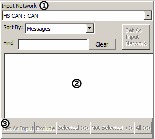
Figure 1 - 1:
- Select Input Network - The input network can be selected from the dropdown menu. The sorting order of messages can be changed to sort by message or sort by ECU. Specific message and signal names can be searched for in the box next to 'Find'.Figure 1 - 1:
- Message and Signal table - Any messages and signals that are part of the selected 'Input Network' will show up hereFigure 1 - 1:
- Input Buttons:
Figure 1: - Selected Messages View:
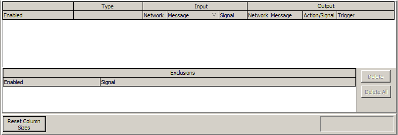
Figure 1: - Outgoing Messages View:
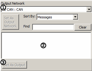
Figure 1 - 4:
- Select Output Network - This functions identically to the 'Select Input Option' above (figure 2 - 1:with the exception that it handles outgoing gateway messages.Figure 1 - 4:
- Output Messages View - This shows any options for outgoing messages for the selected gateway. Depending on the gateway being built, this is where to access outgoing messages to either view the list, or to map them to an incoming message. This will be explained in detail later in the exampleFigure 1 - 4:
- Set as Output - This button functions identically to the 'Set as Input' button (Figure 1 - 2:) with the exception that it handles outgoing gateway messages.
Figure 1: - Setup Panel:
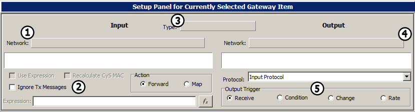
Figure 1 - 5:
- Input Network - The top box shows the current selected input network and the bottom box shows what is being inputted specifically, whether it be a message, a signal, or the entire networkFigure 1 - 5:
- Input Options:Figure 1 - 5:
- Output Type - The type of item being gatewayed will appear up here as Network, Message or SignalFigure 1 - 5:
- Output Network - This functions as the input network, except it specifies the Output Network parametersFigure 1 - 5:
- Output Options: