VSpy 3 Documentation
All DocsProductsLearning CenterSupport
3.9.14
3.9.14
  • 🚗Welcome to the Vehicle Spy Help Documentation
  • Vehicle Spy Introduction
    • Vehicle Spy Overview
      • Vehicle Spy Tour
        • Vehicle Spy Tour 1: Bus Monitor
        • Vehicle Spy Tour 2: Signal Monitoring and Recording
        • Vehicle Spy Tour 3: Flight Recording
        • Vehicle Spy Tour 4: Node/Vehicle Simulation
        • Vehicle Spy Tour 5: Test Automation
        • Vehicle Spy Tour: Summary
    • Other Vehicle Spy Users
    • Vehicle Spy Specifications
    • Vehicle Spy Required Hardware PC System Requirements
    • Vehicle Spy Website
  • Vehicle Spy Tutorials
    • Vehicle Spy Tutorial Files
    • Getting Comfortable with the User Interface
    • Tabs in the User Interface
    • Tutorial 1: Basics of Vehicle Spy
      • Part 1 - Logon Screen
      • Part 2 - Monitor Message Traffic
      • Part 3 - Examine Messages
      • Part 4 - Your Message Specification in Action
      • Part 5 - Filtering Messages
      • Part 6 - More Ways to Filter in Vehicle Spy
      • Part 7 - Message Timestamps and Pausing
      • Part 8 - Save Your Messages View Buffer
      • Part 9 - Clear the Messages View Buffer
      • Part 10 - Exercises
    • Tutorial: Transmit Messages with Vehicle Spy
      • Part 1 - Load the Setup File
      • Part 2 - Enter a Transmit Message
      • Part 3 - Utilize the Alternate Workspace Panels
      • Part 4 - Manually Transmit a Message
      • Part 5 - Periodically Transmit a Message
      • Part 6 - Automatically Respond to a Message
      • Part 7 - Exercises
    • Tutorial: Decode Signals from Messages
      • Part 1 - Load a Setup File
      • Part 2 - Enter a Message
      • Part 3 - Enter an Equation for an Analog Value
      • Part 4 - View Message Data
      • Part 5 - View Message Data with the Signal List and Signal Plot
      • Part 6 - An Introduction to Signal Plot Features
      • Part 7 - Exercises
    • Tutorial: Database Setup
      • Part 1 - Platform Overview
      • Part 2 - Create a Platform
      • Part 3 - Adding Database Files
      • Part 4 - ECU Setup Wizard
      • Part 5 - Diagnostic Decoding
      • Part 6 - Conclusion
    • Tutorial: Basics of Capture Function Block and Graphical Panels
      • Part 1 - Setup the Simulation
      • Part 2 - Setup the Capture Function Blocks
      • Part 3 - Setup the Graphical Panel
      • Part 4 - Conclusion
    • Tutorial: Basics of Scripting and Playback
      • Part 1 - Setup Application Signals
      • Part 2 - Setup the Graphical Panel
      • Part 3 - Setup The Playback Function Block
      • Part 4 - Setup the Script Function Block
      • Part 5 - Summary
    • Tutorial: Request and Save DTC Data
      • Part 1 - Create a Diagnostic Job
      • Part 2 - Create Function Block to Request and Save Data
      • Part 3 - Make a Graphical Panel
      • Part 4 - Request, Save, and View the DTCs
      • Part 5 - Conclusion
    • Tutorial: DPS Programming Automation
      • Part 1 - Create DPS Programming Job
      • Part 2 - Create Function Block to Launch Programming Services
      • Part 3 - Make a Graphical Panel
      • Part 4 - Use the DPS Programming Graphical Panel
      • Part 5 - DPS Programming Automation Conclusion
    • Tutorial: Getting Fancy with Diagnostics
      • Part 1 - Read Data By Identifier Setup
      • Part 2 - Write Data by Identifier Setup
      • Part 3 - Writing the Read DID
      • Part 4 - Request Identifiers using Dynamically Define Data Identifier
      • Part 5 - Request the Dynamic Identifier
      • Part 6 - Conclusion
    • Tutorial: Sort Messages by ECU
      • Part 1 - Start a New Vehicle Spy Application
      • Part 2 - Enter ECU Source IDs to Sort
      • Part 3 - Setup Capture Type Function Blocks
      • Part 4 - Sort the ECU Messages
      • Part 5 - Setup Application Signals
      • Part 6 - Setup Playback Type Function Blocks
      • Part 7 - Setup Script Type Function Blocks
      • Part 8 - Construct a User Dialog
      • Part 9 - Run the Setup
    • Tutorial: Configuring and Using CoreMini
      • Part 1 - Creating a Tx Message
      • Part 2 - Logging Data
      • Part 3 - Loading the Script to the Hardware
      • Part 4 - How to Run the Script
      • Part 5 - Extracting Data
      • Part 6 - Viewing the Data
      • Part 7 - Conclusion
    • Tutorial: Simple Standalone Logging
      • Part 1 - Getting Started
      • Part 2 - Database/Hardware Setup
      • Part 3 - Channels
      • Part 4 - Checking Channel Selection
      • Part 5 - Standalone Logging
      • Part 6 - CoreMini Console
      • Part 7 - Extract Data
      • Part 8 - Conclusion
    • Tutorial: Standalone Video Logging
      • Tutorial: Standalone Video Logging - Part 1 - Setting up the Axis Camera
      • Tutorial: Standalone Video Logging - Part 2 - Setting Up Vehiclescape DAQ
      • Tutorial: Standalone Video Logging - Part 3 - Extracting the Video
    • Tutorial: C Code Interface
      • Part 1 - Create a Project
      • Part 2 - Adding Events
      • Part 3 - Running the Example
      • Part 4 - Debugging
      • Part 5 - Conclusion
    • Tutorial: How to run multiple devices in one VS3 file
      • Part 1 - Enabling Multiple Devices
      • Part 2 - Adding Devices
      • Part 3 - Assigning Devices
      • Part 4 - Syncing Time Across Multiple Devices
  • Tutorial Summary
  • Basic Operation of Vehicle Spy
    • The Logon Screen
    • Menus & Buttons
    • Running and Stopping
    • Data Directory
    • Create, Open, & Save Vehicle Spy Setups
    • Alternate Workspaces
    • Using Window Docking
  • Vehicle Spy Main Menus
    • Main Menu: File
      • The Logon Screen
      • Create, Open, & Save Vehicle Spy Setups
      • Import Function Blocks and Graphical Panels
      • Data Directory
      • Review Buffer
    • Main Menu: Setup
      • Setup a Network
      • Setup Platforms
      • Network Databases
      • ECUs View
        • Edit ECU Diagnostic Database
        • ECU Diagnostic Services Tab
      • Data Cache Disk Streaming
    • Main Menu: Spy Networks
      • Snapshot
      • Messages View
        • Messages View Filter Bar
          • Messages View Custom Filters
        • Messages View Top Toolbar
          • Message Details Pane
          • Reverse Engineering
          • Messages View Timestamping
          • Pause Messages View
          • Save the Buffer
          • Clear the Buffer
        • Messages View Column Headers
        • Messages View Column Filters
        • Messages View Buffer Display
          • Displaying Signals in Messages View
          • Buffer Progress Display
          • Messages View Task Menus
        • Messages View Bottom Toolbar
          • Color Filters
          • Messages View Data Byte Format
          • Messages View Setup
      • Message Editor
        • Messages Editor: Overview
        • Messages Editor: Receive, Transmit, & Database Tables
        • Add and Delete Messages
        • Messages Editor: Cut, Copy, and Paste
        • Messages Editor: Sort and Arrange
        • Messages Editor: Pick a Network
        • Messages Editor: Right Click Menu
        • Message PT, Trgt, and Src
        • Messages Editor: Message Fields
          • Message Key
          • Message Description
          • Message Type
          • Message Arbitration ID
          • Multiframe Message
            • Receive ISO15765-2 Multiframe Message
            • Transmit ISO15765-2 Multiframe Message
          • Message Length
          • Message Data Bytes
            • Transmit Long Messages
          • Message Source Node
          • Receive Message "Tx Msg" Field
          • Message Color
        • Message Signals
          • Live Edit
          • Message Signal Type
          • Message Signal Type Analog
          • Message Signal Type Digital
          • Message Signal Type State Encoded
          • Message Signal Type Text
          • Message Signal Type DTC
          • Understanding Bit and Byte : Bit Positions
          • Message Signal Format and Units
      • Transmit Panel
        • Ways to Transmit Messages
          • Auto Tx and Transmit Rate
        • Add and Delete Transmit Messages
        • Transmit Panel Filter Bar
        • Dynamic Transmit Message Bytes
      • Networks
        • Setup a Network
        • Network Statistics
        • Moving Messages Between Networks
      • TCP/IP
      • FlexRay Controllers
        • FlexRay Controllers: State/Action Tab
        • FlexRay Controllers: Configuration Tab
        • FlexRay Controllers: Registers Tab
      • FlexRay Cycles
      • Diagnostics
        • Diagnostics View
        • Diagnostics Setup
      • Diagnostics over IP (DoIP)
      • Simulator
      • ECUs View
        • GMLAN ECUs
        • ISO 14229 ECUs
        • Keyword 2000 ECUs
    • Main Menu: Measurement
      • VehicleScape DAQ
        • VehicleScape DAQ: Database/Hardware Setup Tab
        • VehicleScape DAQ: Channels Tab
        • VehicleScape DAQ: PC Logging Tab
        • VehicleScape DAQ: Standalone Logging Tab
          • Standalone Logging: Collections and Methods
            • Collections and Methods: Message Capture Method
              • Message Capture Method: Message Collection Options
              • Message Capture Method: Start Options
            • Message Capture Method: Stop Options
              • Message Capture Method: Stop Options: Finish After Collecting Messages or When Expression is True
              • Message Capture Method: Stop Options: Pre/Post Collection
              • Message Capture Method: Stop Options: One Shot Report
            • Message Capture Method: Restart Options
            • Message Capture Method: Upload to Wireless neoVI
            • Collections and Methods: Bus Query Method
            • Collections and Methods: Histogram Method
            • Collections and Methods: Ethernet DAQ Method
          • Standalone Logging: Status Reporting
          • Standalone Logging: Power Management
          • Standalone Logging: Generation Options
        • VehicleScape DAQ: Gateway
        • VehicleScape DAQ: Online Tab
      • Signal Views
        • Signal Plot
        • Signal List
      • Graphical Panels
        • Graphical Panels: Tools
          • Graphical Panel Controls: Common Control Properties
          • Graphical Panel Controls: LED
          • Graphical Panel Controls: Text Display
          • Graphical Panel Controls: Meter
          • Graphical Panel Controls: Function Block Button
          • Graphical Panel Controls: Tx Button
          • Graphical Panel Controls: On/Off Button
          • Graphical Panel Controls: Action Button
          • Graphical Panel Controls: Diag Job Action Button
          • Graphical Panel Controls: Bargraph
          • Graphical Panel Controls: Knob
          • Graphical Panel Controls: Grid
          • Graphical Panel Controls: Numeric Entry
          • Graphical Panel Controls: Graph
          • Graphical Panel Controls: Text Entry
          • Graphical Panel Controls: Graphical Display
          • Graphical Panel Controls: Drop Down List
          • Graphical Panel Controls: Message History
          • Graphical Panel Controls: Flash Control
          • Graphical Panel Controls: Radio Button
          • Graphical Panel Controls: Bitmap Button
          • Graphical Panel Controls: Panel Button
          • Graphical Panel Controls: Hex Edit
        • Graphical Panels: Add or Delete a Tool
        • Graphical Panels: Tool Properties
        • Graphical Panels: Move a Tool
        • Graphical Panels: Resize a Tool
        • Graphical Panels: Format (Align or Resize) a Tool Group
        • Graphical Panels: Add or Delete Panels
        • Graphical Panels: Select and Work With Panels
        • Graphical Panels: Panel Properties
        • Graphical Panels: Lock Panels
        • Floating Panels
      • Logging
      • MEP (XCP/CCP) - Memory Edit Protocol
        • MEP Setup
          • MEP Setup - Properties
          • MEP Setup - Import / Export
          • MEP Setup - DAQ Tables
          • MEP Setup - Security
          • MEP Setup - Memory / Hex / S19
        • MEP Value Editor
        • MEP Curve Editor
        • MEP Map Editor
        • Data Acquisition with CCP/XCP
      • Data Analysis
        • Data Analysis: Main Menus and Toolbar
        • Data Analysis: Zoom Toolbar
        • Data Analysis: X-Axis Input Toolbar and Dialog
        • Data Analysis: Plotter Setup Toolbar
      • Data Analysis: Tool Dialog
        • Data Analysis: Calculated Channels
      • Data Analysis: Plotter Area
        • Data Analysis: Plotter Options
        • Data Analysis: Advanced Plotting Methods
      • Data Analysis: Channel Value Pane
      • Data Analysis: Output Bar
      • GPS Maps
      • Video
    • Main Menu: Embedded Tools
      • ECU Flashing Documentation
        • 1. Introduction
        • 2. CAL Files and DIDs (Parameters)
        • 3. ISO 14229 Security (example)
        • 4. Requirements
        • 5. ECU Flash Designer View
        • 6. ECU Flash Manager View
        • 7. Remote Vehicle ECU Flashing
        • 8. Additional Features: ECU Flashing - EXE
      • DPS Archive Viewer
      • CAN Terminal
      • Intrepid ECU Flasher: Definitions
      • J1939 Address Manager
      • J1939 DTC Monitor
      • BitSmash
    • Main Menu: GMLAN
      • Virtual Networks
      • GM CGI Bus
    • Main Menu: Scripting and Automation
      • Function Blocks
        • Function Blocks Toolbar
        • Function Block List
        • Function Block Start Tab
        • Function Blocks Types
          • Script Type Function Block
          • Script Type Function Block: Script Toolbar
          • Script Type Function Block: Commands
            • Script Type Function Block Command: Clear History
            • Script Type Function Block Command: Clear Stats
            • Script Type Function Block Command: Comment
            • Script Type Function Block Command: CoreMini Action
            • Script Type Function Block Command: DAQ Action
            • Script Type Function Block Command: Diag Job Action
            • Script Type Function Block Command: Function Block Action
            • Script Type Function Block Commands: If, Else, Else If, End If
            • Script Type Function Block Command: Jump If
            • Script Type Function Block Command: Jump To
            • Script Type Function Block Command: Load Message Data
            • Script Type Function Block Command: Log Data
            • Script Type Function Block Commands: Start Loop and End Loop
            • Script Type Function Block Command: Pause
            • Script Type Function Block Command: Read Data
            • Script Type Function Block Command: Set Value
            • Script Type Function Block Command: Set Value If
            • Script Type Function Block Command: Show Panel
            • Script Type Function Block Command: Sleep
            • Script Type Function Block Command: Stop
            • Script Type Function Block Command: Test DTC
            • Script Type Function Block Command: Text API
            • Script Type Function Block Command: Transmit
            • Script Type Function Block Command: Wait For
            • Script Type Function Block Command: Wait Until
          • Script Type Function Block: Resetting the Present Flag
          • Script Type Function Block: Debugging Tools
          • Capture Type Function Block
            • Capture Type Function Block: Filter Tab
            • Capture Type Function Block: Stop and Trigger Tab
            • Capture Type Function Block: Storage Tab
            • Capture Type Function Block: Data Tab
          • Playback Type Function Block
          • Function Blocks Hotkeys
      • C Code Interface
        • Working with the C Code Interface
        • C Code Interface: Functions and Events
          • Functions and Events: Message Objects
          • Functions and Events: Application Signals
          • Functions and Events: Timers
          • Functions and Events: Common Functions and Events
          • Functions and Events: Graphical Panels
          • Functions and Events: Diagnostic Jobs
          • Functions and Events: Function Blocks
          • Functions and Events: Text API
          • Functions and Events: Network Indexes and Statistics
        • C Code Interface: Object Names, Debugging, and Common Mistakes
        • C Code Interface: Advanced Topics
        • C Code Interface: CAPL Conversion
      • Application Signals
        • Application Signals: Save and Restore
      • Text API Terminal
    • Main Menu: Run
    • Main Menu: Tools
      • Utilities: CoreMini Console
        • Utilities: CoreMini Control
        • Utilities: CoreMini Partitions
        • Utilities: CoreMini Advanced Settings
      • Utilities: Extract / Export
        • Utilities: Extract from SD Card
        • Utilities: Export VSB to Other Formats
        • Utilities: Export VSB Convert VSB (with VSDB) to Other Formats V using Command Prompt in Windows
        • Utilities: Export VSB to CSV format using DataExtract.exe
      • Tools: Problem Log
      • Utilities: File Conversions
        • VSB Editor
      • Tools: Utilities
        • Utilities: VS3EXE Generator
        • Utilities: Hardware Acceleration
        • Tools: Performance
        • Tools: Language
      • PLASMA / ION Setup
      • Tools: Options
        • Options: Spy Networks Tab
          • Spy Networks Tab: J1850 VPW Mode
        • Options: Performance Settings
        • Options: Multimedia
          • Multimedia: Joystick Setup
        • Options: Text API Options
        • Options: License System
          • License Upgrade Eligibility
        • Options: GPS Setup
        • Options: Data Directories
        • Options: Regional Settings
    • Main Menu: Help
      • Contact Information - Intrepid Control Systems, Inc.
      • Vehicle Spy Website
  • Shared Features in Vehicle Spy
    • Shared Features: Calculated Signal Editor
      • Shared Features: Calculated Analog or Digital Signals
      • Shared Features: Calculated Text Signals
    • Shared Features: DTC Database
    • Shared Features: Expression Builder
    • Shared Features: Predefined Function Keys
    • Shared Features: Starting with a Selected View
    • Shared Features: Widgets
  • Vehicle Network Interface Hardware
    • Vehicle Network Interface Hardware: neoVI FIRE
      • General Purpose IO
    • Vehicle Network Interface Hardware: neoVI RED
    • Vehicle Network Interface Hardware: neoVI Blue
      • General Purpose IO
    • Vehicle Network Interface Hardware: ValueCAN
      • Vehicle Network Interface Hardware: ValueCAN 4-2
      • Vehicle Network Interface Hardware: ValueCAN 4-4
      • Vehicle Network Interface Hardware: ValueCAN 4-2EL
      • Vehicle Network Interface Hardware: ValueCAN 4 Industrial
    • Vehicle Network Interface Hardware: RAD-wBMS
    • Vehicle Network Interface Hardware: RAD-A2B
    • Vehicle Network Interface Hardware: RAD-Gigastar
    • Vehicle Network Interface Hardware: RAD-Galaxy
    • Vehicle Network Interface Hardware: ValueLOG
    • Getting Started with neoECU
      • neoECU Requirements
      • neoECU 10
        • neoECU 10: IO Map
        • neoECU 10: Loading Scripts Over CAN
        • neoECU 10: Power Up and Buttons
        • neoECU 10: Examples
      • neoECU 12
      • neoECU 20
        • neoECU 20: Configuration
        • neoECU 20: IO Map
        • neoECU 20: Loading Scripts Over USB
        • neoECU 20: Examples
      • neoECU 22
      • neoECU Firmware Updates
      • neoECU Sleep Mode
    • Vehicle Spy Text API
      • Vehicle Spy Text API: ECU Object
      • Vehicle Spy Text API: Labview Interface
    • Vehicle Spy VSB file Spec
  • Application Notes
    • Application Note: CoreMini Partition Logging
      • Logging - Part 1: General Setup
      • Logging - Part 2: Function Block Setup
      • Logging - Part 3: Sending the Script to the Hardware
      • Logging - Part 4: Conclusion
    • Application Note: VehicleScape Standalone Logging
      • Application Note: VehicleScape Standalone Logging - Part 1: Message Collection Options
      • Application Note: VehicleScape Standalone Logging - Part 2: Collection and Restart Options
      • Application Note: VehicleScape Standalone Logging - Part 3: Reporting Options, Power Management and
      • Application Note: VehicleScape Standalone Logging - Part 4: neoVI MOTE Setup
    • Application Note: XCP Driver Example
      • Application Note: XCP Driver Example - Part 1: Process Overview
      • Application Note: XCP Driver Example - Part 2: Example XCP Driver
      • Application Note: XCP Driver Example - Part 3: ECU Simulation and Porting XCP Driver
    • Application Note: neoVI Logging neoECU DAQ
      • Application Note: neoVI Logging neoECU DAQ - Part 1: neoECU Setup
      • Application Note: neoVI Logging neoECU DAQ - Part 2: VehicleScape DAQ
      • Application Note: neoVI Logging neoECU DAQ - Part 3: Review Data
    • Application Note: Using the neoVI MOTE
      • Application Note: Using the neoVI MOTE - Part 1: Messages
      • Application Note: Using the neoVI MOTE - Part 2: Display on Screen
      • Application Note: Using the neoVI MOTE - Part 3: Using the Speaker
      • Application Note: Using the neoVI MOTE - Part 4: Home Screen and Conclusion
    • Application Note: Gateway Builder Tutorial
      • Tutorial - Gateway Builder - Part 1 - Intro
      • Tutorial - Gateway Builder - Part 2 - Gateway Builder Overview
      • Tutorial - Gateway Builder - Part 3 - Add Messages to Gateway Builder
      • Tutorial - Gateway Builder - Part 4 - Gateway Input Actions
      • Tutorial - Gateway Builder - Part 5 - Output Messages, Signals, and Triggers
    • Application Note: Dynamically Manipulating Application Signal Arrays
      • Application Note: Dynamically Manipulating Application Signal Arrays
      • Application Note: Dynamically Manipulating Application Signal Arrays
      • Application Note: Dynamically Manipulating Application Signal Arrays
      • Application Note: Dynamically Manipulating Application Signal Arrays
    • PHY Dashboard
    • Sample Replay Files
  • Contact Us
    • Contact Information - Intrepid Control Systems, Inc.
Powered by GitBook
LogoLogo

Applications

  • Cybersecurity
  • Data Logging
  • Simulate ECU Functions
  • Diagnostics, Testing and Validation

Products

  • Vehicle Network Adapters
  • Data Loggers
  • Software
  • Automotive Ethernet Tools

Support

  • Support Resources
  • Contact Support
  • Class Schedule & Registration
  • Training Video Library

Company

  • About
  • News
  • Events
  • Contact Us

Copyright © 2024 | All Rights Reserved

On this page
  • Enter Expression Area:
  • Expression Builder Area:
  • Data Sources, Data Items, Properties, & Operators:
  • Physical IO Properties
  • Operators and Calculator Panel
Edit on GitHub
  1. Shared Features in Vehicle Spy

Shared Features: Expression Builder

PreviousShared Features: DTC DatabaseNextShared Features: Predefined Function Keys

The Expression Builder is a handy feature that will be used again and again while working with Vehicle Spy. This user friendly dialog builds expressions for many tasks such as controlling , linking signals to Graphical Panel elements, and creating custom filters. The interface is constant throughout Vehicle Spy, so there is no burden of learning dozens of complicated dialogs. Just get familiar with the Expression Builder and that's it! Please refer to Figure 1 below as the features of this dialog are explained further.

Enter Expression Area:

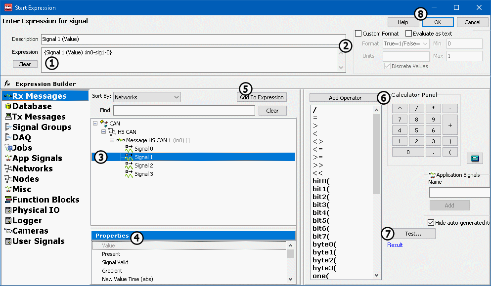
Enter an equation directly into the Expression field at the top of the screen (Figure 1:). This field has a right click menu with standard editing features. Use Evaluate as text (located below the Expression field) for expressions containing only text, or a combination of text and pure data elements without operations performed on them. For example, the expression "The value of engine rpm is {Engine RPM :in1}" should have evaluate as text enabled. If an expression value will be displayed, use the Custom Format options (Figure 1:) to control its , and min/max values.

Expression Builder Area:

Vehicle Spy data sources are selected in the column on the far left. When a source is selected its data items will be displayed in tree form to its right (Figure 1:). When a data item is chosen its available properties are displayed just below the data item tree (Figure 1:). After you select an item and its property you can add it to the Expression field by clicking the Add to Expression button (Figure 1:). Create more complicated expressions using the Add Operator and Calculator Panel functions (Figure 1:) or by typing in the Expression field directly. After your equation is complete, it can be tested by clicking the Test button (Figure 1:). The test result will display below. When you are finished building your expression, click the Ok button (Figure 1:) to return to the previous view. Note that similar to C/C++ or Visual Basic, Boolean type equations are false when they evaluate to zero and true otherwise.

Data Sources, Data Items, Properties, & Operators:

The Expression Builder has many data sources, data items, properties, and operators. Use Table 1 below as a navigation aid to jump to specific tables or related Help Topics.

Table 1: Data Source Jump Table

Jump to Item/Property Table
Jump to Help Topic

n/a

n/a

n/a

Below, Table 2 describes all of the different properties for the different data sources in the Expression Builder. Digital refers to a signal that can be on or off like a switch. Analog refers to a signal that can have many different values like Vehicle Speed.

Table 2: Data Source Properties

Message Properties: Rx Messages, Database, Tx Messages (shared)

Message Property
Type
Description

Present

Digital

Turns true when message is first present on the bus.

Present Toggle

Digital

Toggles True/False every time the message appears on the bus.

Update Rate (rel)

Analog

Time between counts of this message.

Update Rate (abs)

Analog

Time this message appeared on the bus relative to when Vehicle Spy starts.

Per Second

Analog

Rate that the message appears on the bus.

Count

Analog

Number of times that the message appears on the bus.

Change Count

Analog

Returns the number of times the message has changed.

Start Time

Analog

Time that the message first appeared on the bus.

Min Time

Analog

Minimum update rate for the message.

Max Time

Analog

Maximum update rate for the message.

Mean Time

Analog

Mean update rate for the message.

Message Status

Analog

Status flags for the message.

Message ArbID

Analog

ArbID of a CAN type message as listed in the Messages Editor Rx/Tx/Database tables.

Message RTM Frame

Digital

True if the message was a remote frame.

Message PT

Analog

PT byte of the message.

Message Trgt

Analog

Trgt byte of the message.

Message Src

Analog

Src byte of the message.

Message Length

Analog

Number of data bytes in a single frame message.

Message B1 to B8

Analog

Data bytes B1 to B8 of the message.

Message Xtd ID

Digital

True if message has an Extended Arbitration ID.

Message Is Tx Msg

Digital

True if the Rx message was transmitted by Vehicle Spy. Simplifies network gateway logic versus using Has Transmitted because wildcard filters are allowed only on Rx messages.

MultiFrame (MF) Complete

Digital

True if multiframe message completed ok.

Message Data

Analog

Use this for efficient gateway functionality, but not for display purposes. Example: Msg1(Message Data) = Msg2(Message Data).

MultiFrame Flow Control Arb ID

Analog

Arb ID of the flow control frame in a multiframe message.

Message BX

Analog

Message data byte BX, where X = index. (Index 0 = byte B1, index 1 = byte B2, etc.)

Received Transport Layer Payload Length

Analog

Number of data bytes in a multiframe message.

Transport Layer Error Flag

Analog

Non zero values imply transport layer stack detected a problem.

Last Received Arb ID

Analog

Last received ArbID of a message in a Rx or Database table. This is typically the same value as Message ArbID, but not when wildcard "X" bitwise filters are being used in the Messages Editor.

Message Properties: Unique to Tx Messages

Message Property
Type
Description

Any Tx Msg property shared with Rx Msg

n/a

Tx Msg Period Ms

Analog

Periodic rate for the message (in milliseconds).

Tx Msg Periodic On-Off

Digital

Periodic mode of the message (0-normal, 1-periodic).

Has Transmitted

Digital

Becomes true if the message is transmitted by Vehicle Spy.

Signal Properties: Rx Messages, Database, Tx Messages, DAQ, Jobs

Signal Property
Type
Description

Value

Any

Present

Digital

True if the message with the signal has been on the bus.

Signal Valid

Digital

True if the signal valid is current.

Gradient

Analog

Change in value between the last two instances of the signal.

New Value Time (abs)

Analog

Time that the last signal was received.

Start Value

Analog

Initial value of the signal.

Min Value

Analog

Minimum value received.

Max Value

Analog

Maximum value received.

Mean Value

Analog

Mean value of the received signal.

Start Gradient

Analog

Initial change in the signal's value.

Min Gradient

Analog

Smallest change in the signal's value.

Max Gradient

Analog

Largest change in the signal's value.

Mean Gradient

Analog

Mean value of the change in the signal's value.

Raw Value

Analog

Signal Group (Logging) Properties

Signal Group Property
Type
Description

Is Logging

Digital

True only when the signal group is currently being logged.

Log Count

Analog

Number of lines logged for the signal group.

Pre Log Count

Analog

Number of lines collected in the pre-start log buffer.

Time Remaining

Analog

Time remaining in the currently active signal group logging event (seconds).

Total Time

Analog

Total time of the signal group logging event (seconds).

DAQ Properties

DAQ Property
Type
Description

Is Running

Digital

True when the DAQ is running.

Is Triggered

Digital

True when the DAQ is triggered.

Number Msgs Collected

Analog

Number of lines collected by the DAQ.

Job (Diagnostic) Properties

Job Property
Type
Description

Is Running

Digital

True while the job is running.

Number Messages Collected

Analog

Reports total number of messages received during the job.

Is Successful

Digital

True if the job completed successfully.

ECU Response Count

Analog

Number of ECUs that responded to the job.

Total Time Abs

Analog

Total time used to complete the job.

Last 7F Sub Function Excluding 78

Analog

Last negative response sub-function received that was not a $78.

7F Count Excluding 78

Analog

Number of negative responses received excluding sub-function $78.

7F count 78 Response Pending

Analog

Number of negative responses received with sub-function $78.

Application Signal Data Items

Data Item
Type
Description

Application Signal Name

Any

Network Properties

Network Property
Type
Description

Count

Analog

Number of messages for the network.

Rate

Analog

Number of messages per second for the network.

Percent Use

Analog

Percent of network utilization for the network.

Max Rate

Analog

Maximum number of messages per second for the network.

Max Percent Use

Analog

Maximum network utilization for a network.

Error Count

Analog

Number of errors on the network.

Tx Count

Analog

Number of messages transmitted by Vehicle Spy on the network.

Error Rate

Analog

Number of errors per second on the network.

Tx Rate

Analog

Number of messages transmitted per second on the network.

Tx Buffer Fill

Analog

Number of messages in the transmit buffer of the connected hardware on the network.

Enabled

Digital

Enables the network. Some networks cannot be enabled at the same time (ex: LIN2, ISO2, and CGI on FIRE). Assigning a 1 will enable the network and disable other networks that would conflict.

Available

Digital

Read as 1 if network is available on current hardware, 0 otherwise. Useful for CoreMinis designed to run on several different 3G devices.

Fast Wakeup Enable

Digital

Text API Enable

Digital

Bitrate

Analog

Network bitrate in bits per second. Read value represents the current bitrate. Write to signal to change desired bitrate. Valid values for CAN are: 20000, 33333, 50000, 62500, 83333, 100000, 125000, 250000, 500000, 800000, & 1000000. Valid values for LIN, ISO9141, and UART are 39 to 10000000. Valid values for CGI are 115200 and 625000. Not applicable for any other network types.

Auto Bitrate Enable

Digital

Set to 1 to enable auto bitrate. Only supported for "first" two CAN channels of any 3G device.

Wakeup Event Count

Analog

CAN Tx Err Count

Analog

Number of CAN transmit errors on the network.

CAN Rx Err Count

Analog

Number of CAN receive errors on the network.

CAN Controller Mode

Analog

Controller mode if network is CAN. 0 - Normal 1 - Disabled 3 - Listen Only 7 - Listen All

CAN Transceiver Mode

Analog

Transceiver mode if network is CAN. 0 - Auto 1 - On 2 - Off 3 - High Voltage (SWCAN) 4 - High Speed (SWCAN)

CAN TQ SEG1

Analog

CAN time quanta for segment 1. Writing to this signal will change the Bitrate signal.

CAN TQ SEG2

Analog

CAN time quanta for segment 2. Writing to this signal will change the Bitrate signal.

CAN TQ Prop

Analog

CAN time quanta for propagation delay. Writing to this signal will change the Bitrate signal.

CAN Sync

Analog

CAN time quanta for synchronization jump width. Writing to this signal will change the Bitrate signal.

CAN BRP

Analog

CAN baud rate prescaler. Writing to this signal will change the Bitrate signal.

LIN Mode

Analog

Transceiver mode if network is LIN. 0 - Sleep 1 - Slow 2 - Normal 3 - Fast

LIN Master Resistor

Digital

Set to 0 to enable, 1 to disable. (This is not a typo!)

K-Line Message Termination

Digital

Selects how the end of frame is determined if network is K-Line, ISO9141, or Keyword 2000. 0 = Inner Frame Time 1 = GME CIM-SCL (GM Europe Column Integration Module - Steering Column Lock)

K-Line Checksum Enable

Digital

Set to 1 to enable auto appending the 8 bit checksum (byte sum of all bytes in frame). Also enables checksum validation in VSpy3/DLL.

K-Line Rx Inner Frame Spacing

Analog

Value depends upon K-Line Message Termination: If using Inner Frame Time: Value = 2 * P2 min ms (i.e. 50 = 2 * 25 ms) If using GME CIM-SCL: Value = 10 * "t_InterMessage min" ms (i.e. 3 = 10 * 0.3 ms)

K-Line Tx Inner Frame Spacing

Analog

Value depends upon K-Line Message Termination: If using Inner Frame Time: Value = 2 * P3 ms (i.e. 110 = 2 * 55 ms) If using GME CIM-SCL: Value = 10 * "Tx t_InterMessage" ms (i.e. 2 = 10 * 0.2 ms)

K-Line Tx Inner Byte Spacing

Analog

Value depends upon K-Line Message Termination: If using Inner Frame Time: Value = 2 * P4 ms (i.e. 10 = 2 * 5 ms) If using GME CIM-SCL: Value = 10 * "t_InterByte" ms (i.e. 1 = 10 * 0.1 ms)

K-Line Parity

Analog

Selects parity if network is K-Line, ISO9141, or Keyword 2000. 0 - None 1 - Even 2 - Odd

K-Line Enable Tester Resistor

Digital

Set to 1 to enable 510 ohm tester resistor if network is K-Line, ISO9141, or Keyword 2000.

CGI Checksum Enable

Digital

Set to 1 to enable 16 bit checksum if network is CGI.

CGI Rx Inner Frame Spacing (bits)

Analog

Sets receive message inner frame spacing (in bits) if network is CGI.

CGI Tx Inner Frame Spacing (bits)

Analog

Sets transmit message inner frame spacing (in bits) if network is CGI.

SWCAN AutoSwitch Resistor Enable

Analog

Enables SWCAN high speed mode. 0 = Disabled 1 = Autoswitch no resistor 2 = Autoswitch with resistor (default)

UART Tx Register

Analog

Stores data for transmitting on UART.

UART Tx Is Full

Digital

True if the UART transmit buffer is full.

UART Tx is Empty

Digital

True if the UART transmit buffer is empty.

UART Rx Register

Analog

Stores data received from UART.

UART Rx is Full

Digital

True if the UART receive buffer is full.

UART Rx is Empty

Digital

True if the UART receive buffer is empty.

UART Rx Parity Error

Digital

True if a UART parity error is detected.

UART Rx Frame Error

Digital

True if a UART frame error is detected.

UART Rx Overflow Error

Digital

True if a UART overflow error is detected.

UART Rx Clear FIFO

Digital

Clears the UART FIFO receive buffer when set to 1.

UART Error Field

Analog

Reports the Error Status of UART communication 1 = UART_NET_ERROR_TX_MISMATCH Rx does not equal Tx 2 = UART_NET_ERROR_TX_TIMEOUT no Tx ISR 4 = UART_NET_ERROR_TX_FIFO_OVERFLOW Tx FIFO overflow detected 8 = UART_NET_ERROR_RX_FIFO_OVERFLOW Rx FIFO overflow detected 16 = UART_NET_ERROR_RX_PARITY Parity error 32 = UART_NET_ERROR_RX_OVERFLOW Hardware overflow 64 = UART_NET_ERROR_RX_FRAME frame error

Node Properties

Node Property
Type
Description

Count

Analog

Number of messages for the node.

Rate

Analog

Number of messages per second for the node.

Percent Use

Analog

Percent of network utilization for the node.

Max Rate

Analog

Maximum number of messages per second for the node.

Max Percent Use

Analog

Maximum network utilization for a node.

NetMgmt Frame Count

Analog

TBD

NetMgmt Is Simulated

Digital

TBD

Misc Data Items

Misc Data Item
Type
Description

GPS Items

GPS Altitude, Latitude, Longitude, Speed

Analog

GPS data values.

GPS Valid

Digital

True if GPS data is valid.

Input Items

Joystick 1-10

Digital

Joystick XYZ

Analog

Keyboard CTRL

Digital

True while keyboard control key is pressed.

Keyboard F6-F12

Digital

True while corresponding keyboard F6-F12 key is pressed.

neoVI PRO Buttons

Digital

True while corresponding neoVI PRO button is pressed.

Misc Items

Available Disk Space (KB)

Analog

Amount of disk space available, in kilobytes, at the Vehicle Spy exe file location.

Dropped Logged Sectors

Analog

Number of sectors dropped by the SD card logger.

neoVI PRO Outputs

Digital

Set true to activate the neoVI PRO LEDs, Backlight, Buzzer or invert its screen.

Sector Buffers Remaining

Analog

Time Items

Abs Time (Sec)

Analog

Absolute time since Vehicle Spy start button was pressed.

Day

Analog

Day of the month as set on the computer clock.

Day of week

Analog

Numbers 0-6 representing days of the week as set on the computer clock. 0=Sunday, 1=Monday, etc.

Hour

Analog

Hour from 0-23 as set on the computer clock. 0=Midnight, 12=Noon, etc.

Minute

Analog

Minute 0-59 as set on the computer clock.

Month

Analog

Month 1-12 as set on the computer clock.

Second

Analog

Second 0-59 as set on the computer clock.

Time (ms)

Analog

Millisecond value from the Windows TimeGetTime API.

Time Diff

Analog

Year

Analo

4 digit representation of the year as set on the computer clock.

Function Block Properties

Function Block Property
Type
Description

Is Running

Digital

True when the function block is running. Works for any function block type.

Is Triggered

Digital

Number Msgs Collected

Analog

Number of messages collected by a Capture function block.

Script Filter Add Message

Analog

MEP (Memory Edit Protocol) Properties

MEP Property
Type
Description

Value

Any

Physical IO Properties

Physical IO Property
Type
Description

Analog Inputs

Analog Input 1-8

Analog

Reads Analog inputs on supported neoVI devices.

Analog Outputs

Analog Output 1-10

Analog

Sets the Analog outputs on supported neoVI devices.

General neoVI Hardware

Ain Report Interval

Analog

Report interval for analog inputs. (1 to 125 ms)

Device Serial Number

Analog

L Line State

Digital

Sets the L line state.

LED Flash Type

Digital

TBD

LED Group

TBD

TBD

Main Loop

Analog

Main Loop Max

Analog

Power Off Timer

Analog

Time (ms) since the last keep awake event occurred. (Rx msg, USB connect, etc.)

Power Off Timer Reset

Digital

Resets the Power Off Timer to 0.

Relay Group

TBD

TBD

Separation Time Offset

Analog

TBD

Tx Write Index

Analog

TBD

Tx Write Limit

Analog

TBD

Temperature Deg C

Analog

TBD

UART 1 Line State

TBD

TBD

UART 2 Line State

TBD

TBD

LEDs

LED 1-10

Digital

Set true to activate the selected LED. For FIRE, Red, Yellow, and ValueCAN3 hardware LED 1 = red and LED 2 = green.

LIN States

LIN1-6 State

TBD

TBD

Misc IO

Misc IO 1-67 Value

Analog

Sets or Reads the IO states for neoECU Chip.

Misc IO 1-67 Is Output

Digital

Sets the direction of IO on a neoECU Chip.

PWM Inputs

PWM Input 1-8 Value

Digital

Reads the Value of the Pulse to be sent for the duration sent with Pulse Width.

PWM Input 1-8 PWM Frequency (Hz)

Analog

Reads the Frequency of neoECU Devices that support PWM IO

PWM Input 1-8 PWM Duty (%)

Analog

Reads the Duty cycle of neoECU Devices that support PWM IO

PWM Input 1-8 PWM Pulse Width (us)

Ana

Reads the Pulse Width of neoECU Devices that support PWM IO

PWM Input 1-8 PWM Timer Source

Digital

Sets 16 bit timer source resolution for tracking pulse widths in firmware.

So, if pulses are wider than 1.6 ms use timer source value of 0. Firmware defaults timer source to 1.

PWM Outputs

PWM Output 1-8 Value

Digital

Sets the Value of the Pulse to be sent for the duration sent with Pulse Width.

PWM Output 1-8 PWM Frequency (Hz)

Analog

Sets the Frequency of neoECU Devices that support PWM IO

PWM Output 1-8 PWM Duty (%)

Analog

Sets the Duty cycle of neoECU Devices that support PWM IO

PWM Output 1-8 PWM Pulse Width (us)

Analog

Sets the Pulse Width of neoECU Devices that support PWM IO

PWM Output 1-8 PWM Timer Source

Digital

Sets 16 bit timer source resolution for tracking pulse widths in firmware.

So, if pulses are wider than 1.6 ms use timer source value of 0. Firmware defaults timer source to 1.

Power Management

Power Management Mode

Analog

Power Management Network Enables

Analog

If Fast Wakeup is enabled, determines which network is using it. 0 = none 1 = HSCAN only 2 = MSCAN only 3 = HSCAN and MSCAN

Power Management Timeout

Analog

Power Off Timer

Analog

Time (ms) since the last keep awake event occurred. (Rx msg, USB connect, etc.)

Power Off Timer Reset

Digital

Resets the Power Off Timer to 0.

Power Supply

Power Supply Current

Analog

N/A

Power Supply Is On

Digital

Power Supply Voltage

Analog

Relays

Relay 1-8

Digital

Sets Relays on neoECU devices

Switches

Switch 1-8

Digital

Reads Switches on neoECU devices

neoVI FIRE Misc

CGI Bitrate

Analog

CGI network bitrate in bits per second (115200 or 625000). Read value represents the current bitrate. Write to signal to change desired bitrate.

CGI Enable

Digital

Set to 1 to enable the CGI network and disable conflicting networks.

Logging Buffer Index

Analog

MISCIO Report Period

Analog

Report period (ms) of the input/output status message sent on the neoVI device virtual network.

Misc 3-6 Is Analog In

Digital

Sets if that MISC IO channel is an analog input or not.

Network Swap

Digital

Swaps HSCAN and MSCAN when enabled. Useful for applying an HSCAN script to MSCAN. 0 = normal (Tx HSCAN will show Rx on HSCAN) 1 = swapped (Tx HSCAN will show Rx on MSCAN)

Logger (CoreMini) Properties

Logger Property
Type
Description

Available Disk Space (kB)

Analog

Amount of SD card memory available, in kilobytes, at the CoreMini script location.

Dropped Logged Sectors

Analog

Number of sectors dropped by the SD card logger.

Is CoreMini

Digital

Reads as 1 if script is running in CoreMini, otherwise 0.

Logging Buffer Index

Analog

Sector Buffers Remaining

Analog

Operators and Calculator Panel

Table 3: Operators Available in the Expression Editor

+

Add

1+1 is 2

-

Subtract

1-1 is 0

*

Multiply

3*3 is 9

/

Divide

10/3 is 3.333333

^

Exponent

3^2 is 9

=

Equals

2=1 is False

>

Greater Than

5 > 3 is True

<

Less Than

5 < 3 is False

<>

Not Equal To

3 <> 32 is True

<=

Less Than or Equal To

5 <= 5 is True

>=

Greater Than or Equal To

6 >= 5 is True

>>(Arg)

Shift all bits to the right Arg times.

8 >> 1 is 4

<<(Arg)

Shift all bits to the left Arg times.

8 << 2 is 32

bitX(Arg)

Returns True if a specific bit is one

bit1(3) is True

byteX(Arg)

Returns a byte of a multi-byte value

byte0(256) is 0 byte1(256) is 1

one(Arg)

Returns 1 if Arg is true

One(5=5) is 1

and

Logical and Bitwise AND

(2=1) And (3=3) is False

or

Logical and Bitwise Or

(2=1) Or (3=3) is True

not

Logical and Bitwise Not

Not (1=1) is False

xor

Logical and Bitwise Xor

1 Xor 255 is 254

rnd(1)

Returns a random number between 0 and 1

Rnd(1) is 0.234324 (or other num)

abs(Arg)

Absolute Value of Arg

abs(-2) is 2

sin(Arg)

Sine of Arg (radians)

sin(3.141593) is 0

cos(Arg)

Cosine of Arg (radians)

cos(3.141593) is -1

tan(Arg)

Tangent of Arg (radians)

tan(0.785398) is 1

log(Arg)

Natural logarithm of Arg

log(2) is 0.6931471805

log10(Arg)

10 Based logarithm of Arg

log10(100) is 2

exp(Arg)

e (the base of natural logarithms) raised to a power

exp(2) is 7.3890560989

sqr(Arg)

Square root of arg

sqr(49) is 7

int(Arg)

Integer portion of arg

int(3.12434) is 3

mod

Divide two numbers and return only the remainder

19 Mod 6.7 is 5

arcsin(Arg)

Arcsine of Arg (radians)

arcsin(0) is 0

arccos(Arg)

Arccosine of Arg (radians)

arccos(-1) is 3.141593

arctan(Arg)

Arctangent of Arg (radians)

arctan(1) is 0.785398

/

to go to start of Rx Message properties. (Tx Msg properties shared with Rx Msgs are explained there. Properties unique to Tx Msgs are explained here.)

Value AFTER the Messages Editor is applied. The determines the property type.

Value BEFORE the Messages Editor is applied.

Value of the . The data item type depends upon the application signal type. If the signal is in an array, use the index (starts at 0) to access elements within the array.

Enables Fast Wakeup (no missed messages) for the HSCAN or MSCAN networks. ( only) Note: neoVI hardware has more parasitic current draw when this is enabled.

Enables Text API on the selected network. ()

Number of wakeup events triggered by the network. ( only)

True while corresponding button 1-10 is pressed.

Current x, y, z values ranging from 0-65535.

Number of sector buffers remaining. ( only) If the value is zero then there is no more buffering space for incoming messages. If you continue logging data you will cause a buffer overflow.

Provides highly accurate (0.5 - 25 usec) message timing measurement in . Basic script logic is: 1) Wait until both messages are present 2) Set TimeDiff = Msg2.AbsTime - Msg1.AbsTime 3) Set application signal = TimeDiff

True when a Capture function block is .

Adds a message to a Capture function block .

Value of the MEP signal. The data item type depends upon the MEP signal type defined in the .

Serial number of the neoVI hardware. (only)

Duration (ns) of last main process loop in .

Maximum duration (ns) of main process loop in since power up.

Timer Source
Time/Tick (firmware)
Max Pulse Width
Timer Source
Time/Tick (firmware)
Max Pulse Width

Sleep mode of the neoVI hardware. ( only) 0 - Normal Sleep, Manual 1 - Normal Sleep, Timed 2 - Fast Wakeup, Timed 3 - Fast Wakeup, Manual

Quiet time (ms) needed before going to sleep. ( only)

Tells the state of the Power supply on device ( only)

Reads voltage supplied to neoVI Device. ( only)

Index of currently selected partition in SDCARD, used in .

Index of currently selected partition in SDCARD, used in .

Number of sector buffers remaining. ( only) If the value is zero then there is no more buffering space for incoming messages. If you continue logging data you will cause a buffer overflow.

There are many operators available in the Expression Builder. These are listed in Table 3 below. An operator can be added by selecting it from the list and then clicking the Add Operator button. Numbers can be added to your equation with the Calculator Panel (:). Operators and numbers can both be added by typing them directly into the Expression field.

0

6.4 us

419.4304 ms

1

25 ns

1.638400 ms

0

6.4 us

419.4304 ms

1

25 ns

1.638400 ms

Messages Editor
Database
Messages Editor
Message Signals
Logging
VehicleScape DAQ
Diagnostics
Application Signals
Networks
Source Nodes
Function Blocks
Memory Edit Protocol
CoreMini Logging
signal equation
signal type
signal equation
Application Signal
CoreMini
CoreMini only
CoreMini
joystick
joystick
CoreMini
CoreMini
triggered
script filter
A2L file
CoreMini
CoreMini
CoreMini
CoreMini
CoreMini
CoreMini
CoreMini
CoreMini logging
CoreMini logging
CoreMini
Rx Message & Database Properties
Tx Message Properties
Signal Properties
Signal Group (Logging) Properties
DAQ Properties
Job Properties
Application Signal Data Items
Network Properties
Node Properties
Misc Data Items
Function Block Properties
MEP Properties
Physical IO Properties
Logger (CoreMini) Properties
Operators & Calculator Panel
Click HERE
Function Blocks
format and units
Figure 1
Figure 1: The Expression Builder is where you can create an equation using Vehicle Spy data.