VSpy 3 Documentation
All DocsProductsLearning CenterSupport
3.9.14
3.9.14
  • 🚗Welcome to the Vehicle Spy Help Documentation
  • Vehicle Spy Introduction
    • Vehicle Spy Overview
      • Vehicle Spy Tour
        • Vehicle Spy Tour 1: Bus Monitor
        • Vehicle Spy Tour 2: Signal Monitoring and Recording
        • Vehicle Spy Tour 3: Flight Recording
        • Vehicle Spy Tour 4: Node/Vehicle Simulation
        • Vehicle Spy Tour 5: Test Automation
        • Vehicle Spy Tour: Summary
    • Other Vehicle Spy Users
    • Vehicle Spy Specifications
    • Vehicle Spy Required Hardware PC System Requirements
    • Vehicle Spy Website
  • Vehicle Spy Tutorials
    • Vehicle Spy Tutorial Files
    • Getting Comfortable with the User Interface
    • Tabs in the User Interface
    • Tutorial 1: Basics of Vehicle Spy
      • Part 1 - Logon Screen
      • Part 2 - Monitor Message Traffic
      • Part 3 - Examine Messages
      • Part 4 - Your Message Specification in Action
      • Part 5 - Filtering Messages
      • Part 6 - More Ways to Filter in Vehicle Spy
      • Part 7 - Message Timestamps and Pausing
      • Part 8 - Save Your Messages View Buffer
      • Part 9 - Clear the Messages View Buffer
      • Part 10 - Exercises
    • Tutorial: Transmit Messages with Vehicle Spy
      • Part 1 - Load the Setup File
      • Part 2 - Enter a Transmit Message
      • Part 3 - Utilize the Alternate Workspace Panels
      • Part 4 - Manually Transmit a Message
      • Part 5 - Periodically Transmit a Message
      • Part 6 - Automatically Respond to a Message
      • Part 7 - Exercises
    • Tutorial: Decode Signals from Messages
      • Part 1 - Load a Setup File
      • Part 2 - Enter a Message
      • Part 3 - Enter an Equation for an Analog Value
      • Part 4 - View Message Data
      • Part 5 - View Message Data with the Signal List and Signal Plot
      • Part 6 - An Introduction to Signal Plot Features
      • Part 7 - Exercises
    • Tutorial: Database Setup
      • Part 1 - Platform Overview
      • Part 2 - Create a Platform
      • Part 3 - Adding Database Files
      • Part 4 - ECU Setup Wizard
      • Part 5 - Diagnostic Decoding
      • Part 6 - Conclusion
    • Tutorial: Basics of Capture Function Block and Graphical Panels
      • Part 1 - Setup the Simulation
      • Part 2 - Setup the Capture Function Blocks
      • Part 3 - Setup the Graphical Panel
      • Part 4 - Conclusion
    • Tutorial: Basics of Scripting and Playback
      • Part 1 - Setup Application Signals
      • Part 2 - Setup the Graphical Panel
      • Part 3 - Setup The Playback Function Block
      • Part 4 - Setup the Script Function Block
      • Part 5 - Summary
    • Tutorial: Request and Save DTC Data
      • Part 1 - Create a Diagnostic Job
      • Part 2 - Create Function Block to Request and Save Data
      • Part 3 - Make a Graphical Panel
      • Part 4 - Request, Save, and View the DTCs
      • Part 5 - Conclusion
    • Tutorial: DPS Programming Automation
      • Part 1 - Create DPS Programming Job
      • Part 2 - Create Function Block to Launch Programming Services
      • Part 3 - Make a Graphical Panel
      • Part 4 - Use the DPS Programming Graphical Panel
      • Part 5 - DPS Programming Automation Conclusion
    • Tutorial: Getting Fancy with Diagnostics
      • Part 1 - Read Data By Identifier Setup
      • Part 2 - Write Data by Identifier Setup
      • Part 3 - Writing the Read DID
      • Part 4 - Request Identifiers using Dynamically Define Data Identifier
      • Part 5 - Request the Dynamic Identifier
      • Part 6 - Conclusion
    • Tutorial: Sort Messages by ECU
      • Part 1 - Start a New Vehicle Spy Application
      • Part 2 - Enter ECU Source IDs to Sort
      • Part 3 - Setup Capture Type Function Blocks
      • Part 4 - Sort the ECU Messages
      • Part 5 - Setup Application Signals
      • Part 6 - Setup Playback Type Function Blocks
      • Part 7 - Setup Script Type Function Blocks
      • Part 8 - Construct a User Dialog
      • Part 9 - Run the Setup
    • Tutorial: Configuring and Using CoreMini
      • Part 1 - Creating a Tx Message
      • Part 2 - Logging Data
      • Part 3 - Loading the Script to the Hardware
      • Part 4 - How to Run the Script
      • Part 5 - Extracting Data
      • Part 6 - Viewing the Data
      • Part 7 - Conclusion
    • Tutorial: Simple Standalone Logging
      • Part 1 - Getting Started
      • Part 2 - Database/Hardware Setup
      • Part 3 - Channels
      • Part 4 - Checking Channel Selection
      • Part 5 - Standalone Logging
      • Part 6 - CoreMini Console
      • Part 7 - Extract Data
      • Part 8 - Conclusion
    • Tutorial: Standalone Video Logging
      • Tutorial: Standalone Video Logging - Part 1 - Setting up the Axis Camera
      • Tutorial: Standalone Video Logging - Part 2 - Setting Up Vehiclescape DAQ
      • Tutorial: Standalone Video Logging - Part 3 - Extracting the Video
    • Tutorial: C Code Interface
      • Part 1 - Create a Project
      • Part 2 - Adding Events
      • Part 3 - Running the Example
      • Part 4 - Debugging
      • Part 5 - Conclusion
    • Tutorial: How to run multiple devices in one VS3 file
      • Part 1 - Enabling Multiple Devices
      • Part 2 - Adding Devices
      • Part 3 - Assigning Devices
      • Part 4 - Syncing Time Across Multiple Devices
  • Tutorial Summary
  • Basic Operation of Vehicle Spy
    • The Logon Screen
    • Menus & Buttons
    • Running and Stopping
    • Data Directory
    • Create, Open, & Save Vehicle Spy Setups
    • Alternate Workspaces
    • Using Window Docking
  • Vehicle Spy Main Menus
    • Main Menu: File
      • The Logon Screen
      • Create, Open, & Save Vehicle Spy Setups
      • Import Function Blocks and Graphical Panels
      • Data Directory
      • Review Buffer
    • Main Menu: Setup
      • Setup a Network
      • Setup Platforms
      • Network Databases
      • ECUs View
        • Edit ECU Diagnostic Database
        • ECU Diagnostic Services Tab
      • Data Cache Disk Streaming
    • Main Menu: Spy Networks
      • Snapshot
      • Messages View
        • Messages View Filter Bar
          • Messages View Custom Filters
        • Messages View Top Toolbar
          • Message Details Pane
          • Reverse Engineering
          • Messages View Timestamping
          • Pause Messages View
          • Save the Buffer
          • Clear the Buffer
        • Messages View Column Headers
        • Messages View Column Filters
        • Messages View Buffer Display
          • Displaying Signals in Messages View
          • Buffer Progress Display
          • Messages View Task Menus
        • Messages View Bottom Toolbar
          • Color Filters
          • Messages View Data Byte Format
          • Messages View Setup
      • Message Editor
        • Messages Editor: Overview
        • Messages Editor: Receive, Transmit, & Database Tables
        • Add and Delete Messages
        • Messages Editor: Cut, Copy, and Paste
        • Messages Editor: Sort and Arrange
        • Messages Editor: Pick a Network
        • Messages Editor: Right Click Menu
        • Message PT, Trgt, and Src
        • Messages Editor: Message Fields
          • Message Key
          • Message Description
          • Message Type
          • Message Arbitration ID
          • Multiframe Message
            • Receive ISO15765-2 Multiframe Message
            • Transmit ISO15765-2 Multiframe Message
          • Message Length
          • Message Data Bytes
            • Transmit Long Messages
          • Message Source Node
          • Receive Message "Tx Msg" Field
          • Message Color
        • Message Signals
          • Live Edit
          • Message Signal Type
          • Message Signal Type Analog
          • Message Signal Type Digital
          • Message Signal Type State Encoded
          • Message Signal Type Text
          • Message Signal Type DTC
          • Understanding Bit and Byte : Bit Positions
          • Message Signal Format and Units
      • Transmit Panel
        • Ways to Transmit Messages
          • Auto Tx and Transmit Rate
        • Add and Delete Transmit Messages
        • Transmit Panel Filter Bar
        • Dynamic Transmit Message Bytes
      • Networks
        • Setup a Network
        • Network Statistics
        • Moving Messages Between Networks
      • TCP/IP
      • FlexRay Controllers
        • FlexRay Controllers: State/Action Tab
        • FlexRay Controllers: Configuration Tab
        • FlexRay Controllers: Registers Tab
      • FlexRay Cycles
      • Diagnostics
        • Diagnostics View
        • Diagnostics Setup
      • Diagnostics over IP (DoIP)
      • Simulator
      • ECUs View
        • GMLAN ECUs
        • ISO 14229 ECUs
        • Keyword 2000 ECUs
    • Main Menu: Measurement
      • VehicleScape DAQ
        • VehicleScape DAQ: Database/Hardware Setup Tab
        • VehicleScape DAQ: Channels Tab
        • VehicleScape DAQ: PC Logging Tab
        • VehicleScape DAQ: Standalone Logging Tab
          • Standalone Logging: Collections and Methods
            • Collections and Methods: Message Capture Method
              • Message Capture Method: Message Collection Options
              • Message Capture Method: Start Options
            • Message Capture Method: Stop Options
              • Message Capture Method: Stop Options: Finish After Collecting Messages or When Expression is True
              • Message Capture Method: Stop Options: Pre/Post Collection
              • Message Capture Method: Stop Options: One Shot Report
            • Message Capture Method: Restart Options
            • Message Capture Method: Upload to Wireless neoVI
            • Collections and Methods: Bus Query Method
            • Collections and Methods: Histogram Method
            • Collections and Methods: Ethernet DAQ Method
          • Standalone Logging: Status Reporting
          • Standalone Logging: Power Management
          • Standalone Logging: Generation Options
        • VehicleScape DAQ: Gateway
        • VehicleScape DAQ: Online Tab
      • Signal Views
        • Signal Plot
        • Signal List
      • Graphical Panels
        • Graphical Panels: Tools
          • Graphical Panel Controls: Common Control Properties
          • Graphical Panel Controls: LED
          • Graphical Panel Controls: Text Display
          • Graphical Panel Controls: Meter
          • Graphical Panel Controls: Function Block Button
          • Graphical Panel Controls: Tx Button
          • Graphical Panel Controls: On/Off Button
          • Graphical Panel Controls: Action Button
          • Graphical Panel Controls: Diag Job Action Button
          • Graphical Panel Controls: Bargraph
          • Graphical Panel Controls: Knob
          • Graphical Panel Controls: Grid
          • Graphical Panel Controls: Numeric Entry
          • Graphical Panel Controls: Graph
          • Graphical Panel Controls: Text Entry
          • Graphical Panel Controls: Graphical Display
          • Graphical Panel Controls: Drop Down List
          • Graphical Panel Controls: Message History
          • Graphical Panel Controls: Flash Control
          • Graphical Panel Controls: Radio Button
          • Graphical Panel Controls: Bitmap Button
          • Graphical Panel Controls: Panel Button
          • Graphical Panel Controls: Hex Edit
        • Graphical Panels: Add or Delete a Tool
        • Graphical Panels: Tool Properties
        • Graphical Panels: Move a Tool
        • Graphical Panels: Resize a Tool
        • Graphical Panels: Format (Align or Resize) a Tool Group
        • Graphical Panels: Add or Delete Panels
        • Graphical Panels: Select and Work With Panels
        • Graphical Panels: Panel Properties
        • Graphical Panels: Lock Panels
        • Floating Panels
      • Logging
      • MEP (XCP/CCP) - Memory Edit Protocol
        • MEP Setup
          • MEP Setup - Properties
          • MEP Setup - Import / Export
          • MEP Setup - DAQ Tables
          • MEP Setup - Security
          • MEP Setup - Memory / Hex / S19
        • MEP Value Editor
        • MEP Curve Editor
        • MEP Map Editor
        • Data Acquisition with CCP/XCP
      • Data Analysis
        • Data Analysis: Main Menus and Toolbar
        • Data Analysis: Zoom Toolbar
        • Data Analysis: X-Axis Input Toolbar and Dialog
        • Data Analysis: Plotter Setup Toolbar
      • Data Analysis: Tool Dialog
        • Data Analysis: Calculated Channels
      • Data Analysis: Plotter Area
        • Data Analysis: Plotter Options
        • Data Analysis: Advanced Plotting Methods
      • Data Analysis: Channel Value Pane
      • Data Analysis: Output Bar
      • GPS Maps
      • Video
    • Main Menu: Embedded Tools
      • ECU Flashing Documentation
        • 1. Introduction
        • 2. CAL Files and DIDs (Parameters)
        • 3. ISO 14229 Security (example)
        • 4. Requirements
        • 5. ECU Flash Designer View
        • 6. ECU Flash Manager View
        • 7. Remote Vehicle ECU Flashing
        • 8. Additional Features: ECU Flashing - EXE
      • DPS Archive Viewer
      • CAN Terminal
      • Intrepid ECU Flasher: Definitions
      • J1939 Address Manager
      • J1939 DTC Monitor
      • BitSmash
    • Main Menu: GMLAN
      • Virtual Networks
      • GM CGI Bus
    • Main Menu: Scripting and Automation
      • Function Blocks
        • Function Blocks Toolbar
        • Function Block List
        • Function Block Start Tab
        • Function Blocks Types
          • Script Type Function Block
          • Script Type Function Block: Script Toolbar
          • Script Type Function Block: Commands
            • Script Type Function Block Command: Clear History
            • Script Type Function Block Command: Clear Stats
            • Script Type Function Block Command: Comment
            • Script Type Function Block Command: CoreMini Action
            • Script Type Function Block Command: DAQ Action
            • Script Type Function Block Command: Diag Job Action
            • Script Type Function Block Command: Function Block Action
            • Script Type Function Block Commands: If, Else, Else If, End If
            • Script Type Function Block Command: Jump If
            • Script Type Function Block Command: Jump To
            • Script Type Function Block Command: Load Message Data
            • Script Type Function Block Command: Log Data
            • Script Type Function Block Commands: Start Loop and End Loop
            • Script Type Function Block Command: Pause
            • Script Type Function Block Command: Read Data
            • Script Type Function Block Command: Set Value
            • Script Type Function Block Command: Set Value If
            • Script Type Function Block Command: Show Panel
            • Script Type Function Block Command: Sleep
            • Script Type Function Block Command: Stop
            • Script Type Function Block Command: Test DTC
            • Script Type Function Block Command: Text API
            • Script Type Function Block Command: Transmit
            • Script Type Function Block Command: Wait For
            • Script Type Function Block Command: Wait Until
          • Script Type Function Block: Resetting the Present Flag
          • Script Type Function Block: Debugging Tools
          • Capture Type Function Block
            • Capture Type Function Block: Filter Tab
            • Capture Type Function Block: Stop and Trigger Tab
            • Capture Type Function Block: Storage Tab
            • Capture Type Function Block: Data Tab
          • Playback Type Function Block
          • Function Blocks Hotkeys
      • C Code Interface
        • Working with the C Code Interface
        • C Code Interface: Functions and Events
          • Functions and Events: Message Objects
          • Functions and Events: Application Signals
          • Functions and Events: Timers
          • Functions and Events: Common Functions and Events
          • Functions and Events: Graphical Panels
          • Functions and Events: Diagnostic Jobs
          • Functions and Events: Function Blocks
          • Functions and Events: Text API
          • Functions and Events: Network Indexes and Statistics
        • C Code Interface: Object Names, Debugging, and Common Mistakes
        • C Code Interface: Advanced Topics
        • C Code Interface: CAPL Conversion
      • Application Signals
        • Application Signals: Save and Restore
      • Text API Terminal
    • Main Menu: Run
    • Main Menu: Tools
      • Utilities: CoreMini Console
        • Utilities: CoreMini Control
        • Utilities: CoreMini Partitions
        • Utilities: CoreMini Advanced Settings
      • Utilities: Extract / Export
        • Utilities: Extract from SD Card
        • Utilities: Export VSB to Other Formats
        • Utilities: Export VSB Convert VSB (with VSDB) to Other Formats V using Command Prompt in Windows
        • Utilities: Export VSB to CSV format using DataExtract.exe
      • Tools: Problem Log
      • Utilities: File Conversions
        • VSB Editor
      • Tools: Utilities
        • Utilities: VS3EXE Generator
        • Utilities: Hardware Acceleration
        • Tools: Performance
        • Tools: Language
      • PLASMA / ION Setup
      • Tools: Options
        • Options: Spy Networks Tab
          • Spy Networks Tab: J1850 VPW Mode
        • Options: Performance Settings
        • Options: Multimedia
          • Multimedia: Joystick Setup
        • Options: Text API Options
        • Options: License System
          • License Upgrade Eligibility
        • Options: GPS Setup
        • Options: Data Directories
        • Options: Regional Settings
    • Main Menu: Help
      • Contact Information - Intrepid Control Systems, Inc.
      • Vehicle Spy Website
  • Shared Features in Vehicle Spy
    • Shared Features: Calculated Signal Editor
      • Shared Features: Calculated Analog or Digital Signals
      • Shared Features: Calculated Text Signals
    • Shared Features: DTC Database
    • Shared Features: Expression Builder
    • Shared Features: Predefined Function Keys
    • Shared Features: Starting with a Selected View
    • Shared Features: Widgets
  • Vehicle Network Interface Hardware
    • Vehicle Network Interface Hardware: neoVI FIRE
      • General Purpose IO
    • Vehicle Network Interface Hardware: neoVI RED
    • Vehicle Network Interface Hardware: neoVI Blue
      • General Purpose IO
    • Vehicle Network Interface Hardware: ValueCAN
      • Vehicle Network Interface Hardware: ValueCAN 4-2
      • Vehicle Network Interface Hardware: ValueCAN 4-4
      • Vehicle Network Interface Hardware: ValueCAN 4-2EL
      • Vehicle Network Interface Hardware: ValueCAN 4 Industrial
    • Vehicle Network Interface Hardware: RAD-wBMS
    • Vehicle Network Interface Hardware: RAD-A2B
    • Vehicle Network Interface Hardware: RAD-Gigastar
    • Vehicle Network Interface Hardware: RAD-Galaxy
    • Vehicle Network Interface Hardware: ValueLOG
    • Getting Started with neoECU
      • neoECU Requirements
      • neoECU 10
        • neoECU 10: IO Map
        • neoECU 10: Loading Scripts Over CAN
        • neoECU 10: Power Up and Buttons
        • neoECU 10: Examples
      • neoECU 12
      • neoECU 20
        • neoECU 20: Configuration
        • neoECU 20: IO Map
        • neoECU 20: Loading Scripts Over USB
        • neoECU 20: Examples
      • neoECU 22
      • neoECU Firmware Updates
      • neoECU Sleep Mode
    • Vehicle Spy Text API
      • Vehicle Spy Text API: ECU Object
      • Vehicle Spy Text API: Labview Interface
    • Vehicle Spy VSB file Spec
  • Application Notes
    • Application Note: CoreMini Partition Logging
      • Logging - Part 1: General Setup
      • Logging - Part 2: Function Block Setup
      • Logging - Part 3: Sending the Script to the Hardware
      • Logging - Part 4: Conclusion
    • Application Note: VehicleScape Standalone Logging
      • Application Note: VehicleScape Standalone Logging - Part 1: Message Collection Options
      • Application Note: VehicleScape Standalone Logging - Part 2: Collection and Restart Options
      • Application Note: VehicleScape Standalone Logging - Part 3: Reporting Options, Power Management and
      • Application Note: VehicleScape Standalone Logging - Part 4: neoVI MOTE Setup
    • Application Note: XCP Driver Example
      • Application Note: XCP Driver Example - Part 1: Process Overview
      • Application Note: XCP Driver Example - Part 2: Example XCP Driver
      • Application Note: XCP Driver Example - Part 3: ECU Simulation and Porting XCP Driver
    • Application Note: neoVI Logging neoECU DAQ
      • Application Note: neoVI Logging neoECU DAQ - Part 1: neoECU Setup
      • Application Note: neoVI Logging neoECU DAQ - Part 2: VehicleScape DAQ
      • Application Note: neoVI Logging neoECU DAQ - Part 3: Review Data
    • Application Note: Using the neoVI MOTE
      • Application Note: Using the neoVI MOTE - Part 1: Messages
      • Application Note: Using the neoVI MOTE - Part 2: Display on Screen
      • Application Note: Using the neoVI MOTE - Part 3: Using the Speaker
      • Application Note: Using the neoVI MOTE - Part 4: Home Screen and Conclusion
    • Application Note: Gateway Builder Tutorial
      • Tutorial - Gateway Builder - Part 1 - Intro
      • Tutorial - Gateway Builder - Part 2 - Gateway Builder Overview
      • Tutorial - Gateway Builder - Part 3 - Add Messages to Gateway Builder
      • Tutorial - Gateway Builder - Part 4 - Gateway Input Actions
      • Tutorial - Gateway Builder - Part 5 - Output Messages, Signals, and Triggers
    • Application Note: Dynamically Manipulating Application Signal Arrays
      • Application Note: Dynamically Manipulating Application Signal Arrays
      • Application Note: Dynamically Manipulating Application Signal Arrays
      • Application Note: Dynamically Manipulating Application Signal Arrays
      • Application Note: Dynamically Manipulating Application Signal Arrays
    • PHY Dashboard
    • Sample Replay Files
  • Contact Us
    • Contact Information - Intrepid Control Systems, Inc.
Powered by GitBook
LogoLogo

Applications

  • Cybersecurity
  • Data Logging
  • Simulate ECU Functions
  • Diagnostics, Testing and Validation

Products

  • Vehicle Network Adapters
  • Data Loggers
  • Software
  • Automotive Ethernet Tools

Support

  • Support Resources
  • Contact Support
  • Class Schedule & Registration
  • Training Video Library

Company

  • About
  • News
  • Events
  • Contact Us

Copyright © 2024 | All Rights Reserved

On this page
  • ECU Long Description & Checkboxes:
  • CAN Identifiers:
  • ECU Upload / Download:
  • ECU State:
  • DAQ Delays:
  • Network:
  • ASAP2:
  • On Start Memory Load:
  • Communication Protocol:
  • CCP Event Setup:
Edit on GitHub
  1. Vehicle Spy Main Menus
  2. Main Menu: Measurement
  3. MEP (XCP/CCP) - Memory Edit Protocol
  4. MEP Setup

MEP Setup - Properties

PreviousMEP SetupNextMEP Setup - Import / Export

Please refer to the numbered areas in Figure 1 below as the Properties tab features are explained.

ECU Long Description & Checkboxes:

The ECU Long Description field displays the ECU description from the A2L file. The checkboxes below the description control various features:

  • Generate Read for every Write - read back and verify data after every calibration written to the ECU.

  • Upload memory on characteristic open - upload and display the latest data from the ECU when a calibration is opened for editing.

  • Intel address encoding - use Intel byte ordering (most significant byte last) for memory addressing.

  • Auto start MEP when VSpy goes online - start VSpy in "Run with MEP" mode everytime it goes online.

  • SHORT_UP Supported - enable if the ECU supports the Short_Upload command (CCP $0F or XCP $F4). This setting is typically set by the A2L file.

CAN Identifiers:

CAN IDs of the CCP requests transmitted by MEP and the responses received from the ECU. In some cases, a secondary Station ID is also used to properly address an ECU.

ECU Upload / Download:

Click the "Force upload from ECU" button to update all MEP calibration and measurements with the current data from the ECU. Click the "Force download to ECU" button to update all ECU calibrations with the current data in MEP. A status bar indicates the progress of the upload or download event.

ECU State:

Click the Connect/Disconnect button to start and stop the CCP/XCP link between MEP and the ECU. The current state of the CCP/XCP connection is displayed next to the button. If enabled "Automatically Reconnect" will attempt to reconnect if a disconnect is detected.

DAQ Delays:

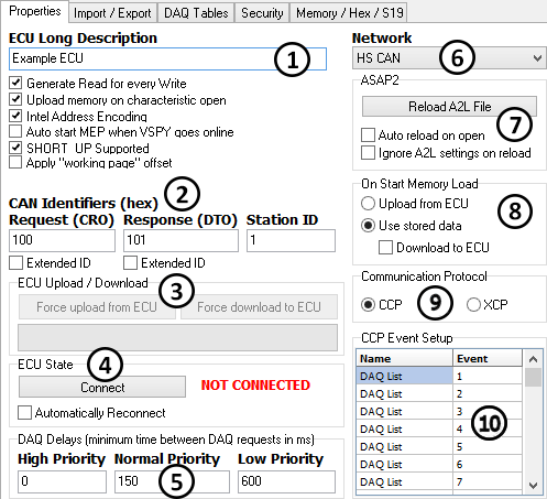
Please continue to refer to Figure 1 as the remaining Properties tab features are explained.

These actions (when enabled) will occur every time Vehicle Spy goes online in MEP mode:

  • Upload from ECU - update MEP calibrations and measurements with data uploaded from the ECU.

  • Use stored data - do nothing and use whatever data is currently in MEP.

  • Download to ECU - update ECU calibrations with data from MEP downloaded to the ECU.

Select between CCP (CAN Calibration Protocol) or XCP (Universal Calibration Protocol). Each protocol has a command set and requirements established by ASAM specifications that define the link between Vehicle Spy MEP and the ECU.

If no events are shown then you can create and edit them using the mouse right click menu. Note that events are optional though and not all ECUs support them. The number (in decimal) in the "Event" column is specific to an ECU's implementation and might not work if it is not part of the original A2L file.

These delay times are used by the High/Normal/Low priorities in with CCP/XCP. Lower delay times will make measurements appear closer to "real time", but also take up more network bandwidth and ECU resources.

Network:

Determines which that MEP will use for the CCP link with the ECU.

ASAP2:

Click the "Reload A2L File" button to remap the memory address and size of all items in the A2L data item tree based upon the A2L file selected. This can save setup time if memory mapping has changed in the A2L file. If "Auto reload on open" is enabled then the A2L file is reloaded everytime the Vehicle Spy is opened.

On Start Memory Load:

Communication Protocol:

CCP Event Setup:

This table lists any events defined in the A2L file. CCP Events are used for with CCP/XCP.

standard data acquisition
Network
vs3 setup file
event based data acquisition
MEP Setup
Figure 1: The MEP Setup Properties tab